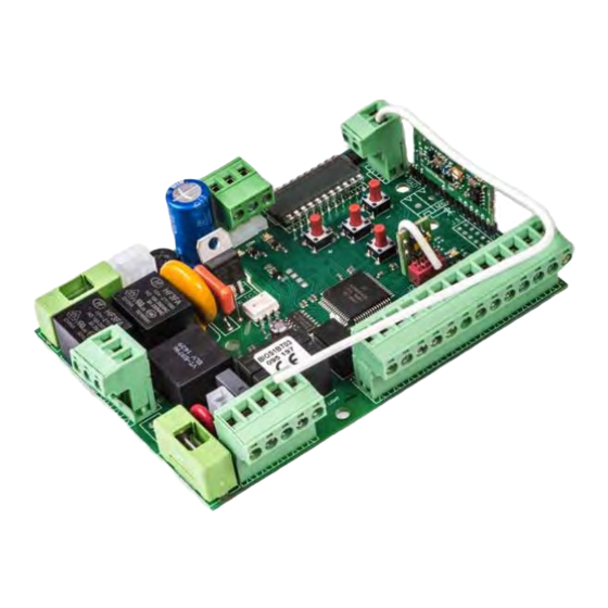
Allmatic BIOS1 Kurulum Kılavuzu - Sayfa 7
Kontrol Ünitesi Allmatic BIOS1 için çevrimiçi göz atın veya pdf Kurulum Kılavuzu indirin. Allmatic BIOS1 12 sayfaları. Battery charging kit
Ayrıca Allmatic BIOS1 için: Kurulum (2 sayfalar)

6.2 Advanced menu:
MENU
First coupling between Bluetooth device and control unit
Electrical brake activation time
.
.
EL EL
EL
EL
F F F F
0 = disabled
1 - 100= enabled
Functioning of PHOTO1 moving from closed
.
.
Sp
Sp Sp
Sp
h h h h
0 = Check PHOTO1
1 = The gate opens also with PHOTO1 busy
Functioning of PHOTO2
.
.
Ph
Ph
2 2 2 2
Ph Ph
0 = Enabled in opening and closing OP/CL
1 = Enabled only in opening OP
Photocells test
0 = disabled
.
.
tP
tP
h h h h
tP tP
1 = enabled PHOTO1
2 = enabled PHOTO2
3 = enabled PHOTO1 and PHOTO2
Safety edge type
.
.
Ed
Ed Ed
Ed
m m m m
0 = contact (NC)
1 = resistive (8k2)
Operation mode of safety edge
0= working only in closing with inversion of movement
.
.
iE
iE iE
iE
d d d d
1 = stops the automation (both opening and closing) and free the obstacle (short
inversion)
Safety edge test
.
.
tE
tE tE
tE
d d d d
0 = disabled
1 = enabled
.
.
LP LP
LP
LP
o o o o
Partial opening
.
.
tP
tP
tP tP
C C C C
Auto reclosing time from partial opening (0 = disabled)
Blinker output mode
.
.
fp fp
fp
fp
r r r r
0 = Fix
1 = Blinking
.
.
tP
tP
tP tP
r r r r
Pre-flashing time (0 = disabled)
Courtesy ligth settings
0 = At the end of movement for a TCY time
1 = On if the gate is not closed + TCY time
.
.
FC
FC FC
FC
Y Y Y Y
2 = On if courtesy light timer (TCY) not expired
3 = Open gate light on/off
4 = Open gate light with proportional flashing
.
.
tC tC
tC
tC
Y Y Y Y
Courtesy light time
Dead-man
.
.
dE
dE
A A A A
dE dE
0 = disabled
1 = enabled
Setting threshold of cycles for assistance request. Once limit is reached the next
.
.
SE
SE SE
SE
R R R R
cycles will be done with fast blinking (only if FPr enabled) (0 = disabled)
Continuous blinking for assistance request (done only with closed gate).
.
.
SE
SE
F F F F
SE SE
0 = disabled
1 = enabled
Viewing of the memory location for a single transmitter
Cancellation of a single transmitter
Restore defaul settings, enter to modify the parameter and then keep pressed the
.
.
dE
dE
dE dE
F F F F
MENU button, a count down appears that ends with don on the display
Cancelling all transmitters, enter to modify the parameter and then keep pressed
.
.
tr
tr
F F F F
tr tr
the MENU button, a count down appears that ends with don on the display
6-1622241
rev.6
04/12/2018
DESCRIPTION
ITA
ENG
FRA
SELECTABLE
ESP
DEU
POR
VALUES
DEFAULT
min-max
0-100
0
0-1
1
0-1
0
0-3
0
0-1
0
0-1
0
0-1
0
0-100
30
0-900
20
0-1
1
0-10
0
0-4
0
0-900
0
0-1
0
0-100
0
0-1
0
0-999
0-999
UNITS
x0.01 s
%
s
s
s
x1000
cicli
7 / 12
