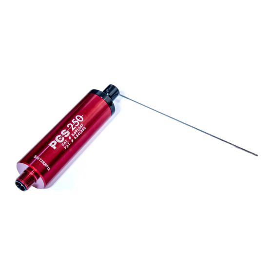
Allora Positive Contact PCS-250 Kurulum Talimatları Kılavuzu - Sayfa 9
Aksesuarlar Allora Positive Contact PCS-250 için çevrimiçi göz atın veya pdf Kurulum Talimatları Kılavuzu indirin. Allora Positive Contact PCS-250 12 sayfaları.

NO POWER TO TCU-250 (No lights illuminated when TCU-250 is powered up and no power to PCS-250.)
• If 115VAC, is the power supply supplied by Allora being used?
• Is there a clean 24VDC being supplied to the power terminals on the TCU-250?
• Is there no more than two TCU-250's running on one power supply?
• Is there 110-120VAC being supplied to the power supply?
• Is the power supply sending 24VDC to the power terminals on the TCU-250?
NO POWER TO PCS-250
• Are one or more lights on the TCU-250 illuminated?
• If not, see No Power to TCU-250
• Is the PCS-250 connected properly?
• Color coded wires of cable should be attached tot he correct terminals on the TCU-250.
• Cable should be screwed tight to the PCS-250 connector.
• The inside of the PCS-250 connector should be dry.
• Manually move the sensing needle away from the start position. Does the sensing needle return to the start
position on its own?
• Is there approximately 4.1VDC across the blue and black terminals on the TCU-250? (The PCS-250
must remain connected to TCU-250 for this measurement.)
• Is there 24VDC across the Power terminals on the TCU-250?
• If not, see No Power to TCU-250
NO FAULT SIGNAL WHEN TOOL IS BROKEN OR FAULT SIGNAL WHEN TOOL IS OKAY
• Was the TCU-250 taught the tool's position?
• To teach the TCU-250, press and release the teach button. The yellow teach light will illuminate.
Press and release the teach button a second time, or give the TCU-250 a start signal. The TCU-250
will run through one cycle, the yellow light will turn off, and the green light will illuminate.
The TCU-250 is now taught that tool's current position.
• Is the tool within the PCS-250's swing angle?
• The sensing needle's tip should extend over the tool's centerline
• The sensing needle should contact the tool at least 1.60mm from the tool's tip.
• Is the sensing needle supplied by Allora being used?
• Is the clamping collar tight on the PCS-250?
• Is the swing arm assembly tight on the PCS-250?
• Is there enough time set on the TCU-250 for the PCS-250 to reach its full swing angle?
• Have any objects obstructing the swing angle of the PCS-250 been removed?
• With power disconnected from PCS-250, can the sensing needle be moved freely back and forth without any
binding?
• Look for metal chips which may be packed around the seals on the PCS-250 or between the PCS-250
and the swing arm assembly.
• Look for large chip "bird's nests" that may be getting caught on the PCS-250, or on the tool.
• Is the PCS-250 connected properly?
• Color coded wires of cable should be attached to the correct terminals on the TCU-250.
• Cable should be screwed tight to the PCS-250 connector.
• The inside of the PCS-250 connector should be dry.
• Is the PCS-250 returning to its start position at the end of each cycle?
• The V-seal in the swing arm assembly provides additional protection against contaminants and should not be
removed in most applications. The V-seal may however restrict the sensors motion when the swing rate is set
on "LO". If your application does not allow "HI" rate operation, you may remove the V-seal from the swing
arm assembly to determine if this solves the problem.
PCS-250 System
Trouble Shooting Guide
Page 8
