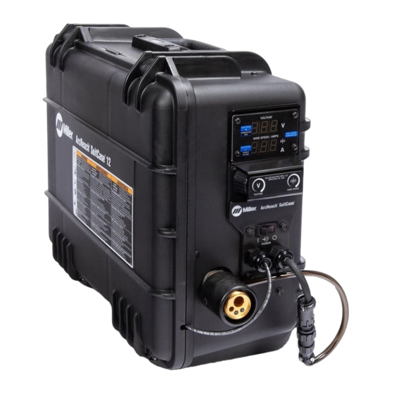
Miller ArcReach SuitCase 12 CE Kullanıcı El Kitabı - Sayfa 31
Kaynak Sistemi Miller ArcReach SuitCase 12 CE için çevrimiçi göz atın veya pdf Kullanıcı El Kitabı indirin. Miller ArcReach SuitCase 12 CE 48 sayfaları.

�
Complete Parts List is available at www.MillerWelds.com
DIP Switch Settings
Display Hold OFF - Set switch 1 so the depressed section is toward OPEN as labeled on the switch.
Displays will not hold values. The voltage displayed while welding is an average reading over a time span of 6 to 8
seconds. If the weld time is less than 8 seconds, the voltage displayed may not be accurate.
Display Hold ON (Factory Default) - Set switch 1 so the depressed section is toward 1 as labeled on the switch.
Displays will hold their last value for five seconds after the trigger is released. The voltage displayed while welding is
an average reading over a time span of 6 to 8 seconds. If the weld time is less than 8 seconds, the voltage displayed
may not be accurate.
Display Amperage - Set switch 2 so the depressed section is toward OPEN as labeled on the switch.
Wire Speed / Amps Display will display Amps while welding and Wire Speed while not welding. If the hold function is
enabled, Amps will be displayed during hold also.
Do Not Display Amperage (Factory Default) - Set switch 2 so the depressed section is toward 2 as labeled on the
switch.
Wire Speed / Amps Display will display only Wire Speed.
Wire Speed - Meters Per Minute - Set switch 3 so the depressed section is toward OPEN as labeled on the switch.
Displays Wire Speed in Meters per Minute.
Wire Speed - Inches Per Minute - Set switch 3 so the depressed section is toward 3 as labeled on the switch.
Displays Wire Speed in Inches per Minute.
Wire feeds during ArcReach association (Factory Default) - Set switch 4 so the depressed section is toward 4 as
labeled on the switch.
This will allow wire to feed when the trigger is pulled and the association process is taking place.
This mode must be used when the feeder is not expected to associate with an ArcReach control, or an ArcReach com-
patible welding power source. This could be when using a non-ArcReach compatible power source or if the feeder
CC/CV switch is set to CC mode.
Wire does not feed during ArcReach association - Set switch 4 so the depressed section is toward OPEN as la-
beled on the switch.
This will prevent wire from feeding when the trigger is pulled and the association process is taking place.
OM-278792 Page 25
