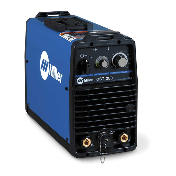
Miller CST 280 Kullanıcı El Kitabı - Sayfa 32
Kaynak Sistemi Miller CST 280 için çevrimiçi göz atın veya pdf Kullanıcı El Kitabı indirin. Miller CST 280 48 sayfaları. Dual rack kit
Ayrıca Miller CST 280 için: Kullanıcı El Kitabı (28 sayfalar)

5-3. Troubleshooting
Repeated LED Flashes Indicate
Status
Blue
Yellow
None
None
Flashes Con-
0
tinuously
6
0
4
0
OM-217 655 Page 28
1
2
Red (LED3
Trouble
on PC3)
No weld output;
unit completely
None
inoperative.
7
No weld output.
1
No weld output.
8
No weld output.
Possible Causes
Line Disconnect open.
Blown fuses.
Improper input connections.
Fuse F1 on PC2 blown.
Line voltage too high or
too low.
Unit is linked incorrectly.
Not ready.
Buss voltage imbalance.
No primary lfb.
Failed output diode(s).
Current latch.
Failed boost inductor.
Failed LEM.
Open connection be-
tween LEM and PC1.
Shorted boost relay.
Boost relay does not
deenergize after termina-
Voltage latch.
tion of weld.
Voltage in excess of
100V from another
source applied across
output studs.
1
Output LED (Blue)
2
High Temperature LED
(Yellow)
803 942-A
Remedy
Place line disconnect switch in
on position (see Section 3-14 or
3-15).
Check and replace line fuses, if
necessary, or reset circuit
breaker (see Section 3-14 or
3-15).
Check for proper input connec-
tions (see Section 3-12 or 3-13).
Check and replace F1.
Line voltage must be ±10%.
Check line voltage and link ac-
cordingly.
Check DC buss caps and PC2,
and replace if necessary.
Check CT1 and wiring for an
open condition.
Check for shorts or opens in
wiring.
Replace boost inductor if neces-
sary.
Replace LEM if necessary.
Inspect all wiring and connec-
tions.
Check for a shorted relay or wir-
ing.
Check PC1.
Check for external voltage
sources.
