Miller XMT 456 CC/CV Kullanıcı El Kitabı - Sayfa 22
Kaynak Sistemi Miller XMT 456 CC/CV için çevrimiçi göz atın veya pdf Kullanıcı El Kitabı indirin. Miller XMT 456 CC/CV 40 sayfaları.
4-3. Meter Functions For Invision 456P
NOTE
Mode
MIG
Pulsed
MIG
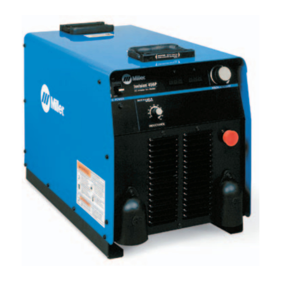
4-4. Front Panel Controls For XMT 456 CC/CV
1
Power Switch
.
The fan motor is thermostatically
controlled and only runs when cooling is
needed.
2
Voltmeter (see Section 4-5)
3
Ammeter (see Section 4-5)
4
V/A (Voltage/Amperage) Adjust Control
5
Voltage/Amperage Control Switch
For front panel control, place switch in Panel
position and use the V/A Adjust control.
For remote control, make connections to Re-
mote 14 receptacle, and place switch in Re-
mote position. In most modes, remote control
is a percent of the V/A Adjust control setting.
Value selected on V/A Adjust is maximum
available on remote. In the MIG mode, remote
control provides full range of unit output re-
gardless of V/A Adjust control setting.
6
Mode Switch
The Mode switch setting determines both the
1
8
OM-2232 Page 18
The meters display the actual weld output values for approximately three seconds
after the arc is broken.
Meter Reading At Idle
V
24.5
Preset Volts
Blank
V
PPP
PPP
Pulse Display
Pulse Display
process and output On/Off control (see Sec-
tion 4-6). Source of control (panel or remote)
for the amount of output is selected on the V/A
Control switch.
For Air Carbon Arc (CAC-A) cutting and goug-
ing, place switch in the Stick position. For best
results, place Inductance/Dig control in the
maximum position.
7
Inductance/Dig Control
Control adjusts Dig when the Stick or CC
mode is selected on the Mode switch. When
set towards minimum, short-circuit amperage
at low arc voltage is the same as normal weld-
ing amperage.
When set towards maximum, short-circuit
amperage is increased at low arc voltage to
assist with arc starts as well as reduce stick-
ing while welding (see volt-ampere curves in
Section 3-3).
7
Meter Reading While Welding
A
24.5
Actual Volts
A
24.5
Actual Volts
Select setting best suited for application.
Control adjusts inductance when MIG posi-
tion is selected on the Mode switch. Induc-
tance determines the "wetness" of the weld
puddle. When set towards maximum, "wet-
ness" (puddle fluidity) increases.
When Pulsed MIG, or one of the TIG modes
is selected, this control is not functional.
8
Sockets 1 and 2 are connected in parallel with
the Power switch. For remote On/Off control,
connect a suitable plug from a remote switch
to the receptacle and place front panel Power
switch in Off position. Unit can then be turned
On and Off through the use of the remote
switch.
2
6
V
A
250
Actual Amps
V
A
250
Actual Amps
Remote On/Off Receptacle (An Option
On 230/460 Volt Models)
4
3
5
196 446