Burkert 2510 Kullanım Talimatları Kılavuzu - Sayfa 7
Valf Konumlandırıcılar Burkert 2510 için çevrimiçi göz atın veya pdf Kullanım Talimatları Kılavuzu indirin. Burkert 2510 13 sayfaları. Device socket
Ayrıca Burkert 2510 için: Kullanım Talimatları (5 sayfalar), Kullanım Talimatları (5 sayfalar), Kullanım Talimatları (5 sayfalar), Kullanım Talimatları Kılavuzu (6 sayfalar)
6.2
Electrical data
Profile S-B.F.F
Supply voltage
29.5 - 31.5 V according to ASI specifi-
cation (PELV)
Max. power consumption From AS-Interface
With electronics
10 mA
Bus-powered (elec-
300 mA
tronics, valve, sensors)
Externally powered
80 mA
(electronics, sensors)
Output voltage
24 V ±10%
6.3
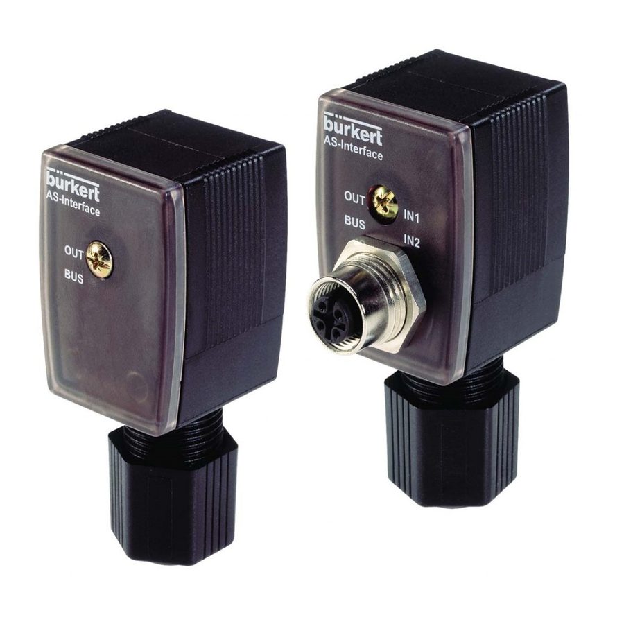
Electrical connection
Figure 2: Electrical connection
Profile l S-B.A.E
10 mA
120 mA
-
Socket M 12 (sensor), 4-pin
cable plug with feedback input
Round plug M 12
(AS-Interface), 4-pin
6.4
Connection of socket and plug
M12 socket, 4-pin
PIN Assignment
1
3
4
2
3
2
1
4
Two sensors with a Y-distributor can be connected via the M
12 socket.
Two sensors (two or three wires) can be connected via a DUO
connector if there is external power supply.
M12 plug, 4-pin
PIN Assignment
3
1
2
3
4
2
4
1
1)
Only for externally supplied cable plugs
English
+ 24 V sensor supply
Sensor input 2
GND
Sensor input 1
AS-Interface Bus+
0 V
1)
AS-Interface Bus-
24 V
1)
7