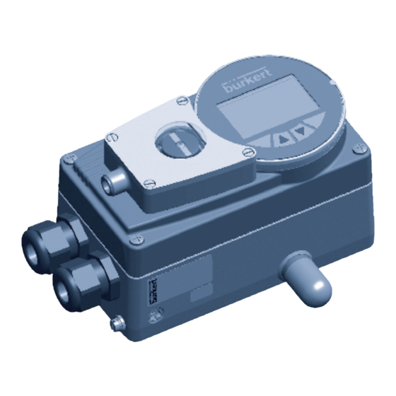
Burkert 8791 Montaj Talimatları Kılavuzu - Sayfa 4
Valf Konumlandırıcılar Burkert 8791 için çevrimiçi göz atın veya pdf Montaj Talimatları Kılavuzu indirin. Burkert 8791 16 sayfaları. External position feedback option with inductive proximity
switch
Ayrıca Burkert 8791 için: Ek Talimatlar (12 sayfalar), Montaj Talimatları Kılavuzu (16 sayfalar)
Step 2: Connect external position indicator
→
Gently pull the cover of the standard position indicator
out of the housing cover (see Fig. 2: ).
→
Close housing cover
note!
Display element may be damaged if the housing
cover is closed carelessly.
When the external position feedback is installed, ensure
that the housing cover is not shifted or damaged when
closing the display element.
•
When closing the housing cover, lift it slightly to pre-
vent it from touching the display element.
→
Place the external position indicator in the round recess
of the housing cover and press down until it engages
(see Fig. 2: ) .
Installation is now complete.
Next connect the external position feedback to the power
supply, as described in the following chapter.
english
12
8.
elecTrical connecTion
Proximity switch 1
Fig. 3:
Electrical connection
english
14
Proximity switch 2
2
1
3
4
Cover
for standard
display element
Fig. 2:
Connecting external position indicator
Pin Configu-
External circuit / signal level
ration
1
Supply
+10 V ... +30 V
10 ... 30 V
2
Switching
+10 V ... +30 V
output (NO)
Proximity
switch 1
3
GND
GND
4
Switching
+10 V ... +30 V
output
(NO)
Proximity
switch 2
Tab. 1:
Electrical connection
Type 8791, 8792, 8793
External position
indicator
Housing cover
english
13
1 10 ... 30 V
2 Open /
10 ... 30 V
3 GND
4 Open /
10 ... 30 V
english
15