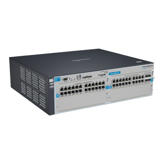
HP ProCurve 4208vl-96 Kurulum Kılavuzu - Sayfa 4
Anahtar HP ProCurve 4208vl-96 için çevrimiçi göz atın veya pdf Kurulum Kılavuzu indirin. HP ProCurve 4208vl-96 13 sayfaları. Hp procurve 4204vl: reference guide
Ayrıca HP ProCurve 4208vl-96 için: Teknik Özellikler (22 sayfalar), Veri Sayfası (10 sayfalar), Hızlı Referans Kılavuzu (44 sayfalar)

9/18/2020
Item Number
1
2
2. The module is fully inserted when the module bulkhead is contacting,or very close to contacting the face of the switch.
Figure 2: Tighten module retaining screws
Item Number
Description
1
The module is fully inserted when the module bulkhead is contacting,or very close to contacting the face of the switch
2
Retaining screws
3. Tighten the retaining screws on the module until they are secure, but do not overtighten them.
top
Install second power supply (Optional)
A second, load-sharing redundant power supply can be installed in the back of the switch. To provide true redundancy, this second power
supply should be connected to a different AC power source from the other supply. Then, if one AC power source fails, the switch will
continue to run. Each supply provides enough power to operate afully loaded switch, so even if one fails, the switch will continue to
operate normally.
Install the second power supply into power slot number 2 as shown in figure 3.
The slot cover can be removed with either a flat-bladed or Torx T-10 screwdriver.Retain the slot cover for future use.
CAUTION: The switch power supplies are hot swappable; they can be installed while the switch is receiving power from the
supply in the other slot. But, as indicatedby the caution statement on the power supply, the supply must not beconnected to AC
power before being installed.
For safety and proper switch cooling, if either of the power supply slots arenot being used, make sure to attach the cover plate
over the slot.
For installation details, see the instructions in the manual that comes with the power supply.
1. Insert the power supply into the opening, then slide it all the way in until it connects to the switch.The power supply face plate will be
flush with the back face of the switch.
Figure 3: Installing a power supply
HPE 4200 vl Switch Series - Installation
Description
Guides
Low-force connector
4/12
