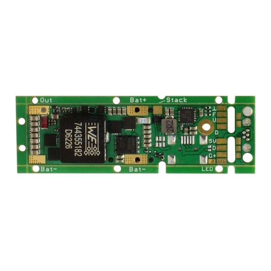
dicodes FL80 Manuel - Sayfa 10
Kontrolör dicodes FL80 için çevrimiçi göz atın veya pdf Manuel indirin. dicodes FL80 11 sayfaları. Electronic circuit board

Pin 1 Fire Button
Pin 2 Up Button
Pin 3 Down Button
Pin 4 Reserved, do not connect
Pin 5 Reserved, do not connect
Pin 6 GND
Accidentally connecting a FFC cable from an external button to the USB-FPC plug does not
harm the board, but be careful: if J2 is closed and an external USB source is connected to the
Mini-USB, although this should not be the configuration when J2 is closed, then, when
pressing the Fire or the Up-button, the external source is shorted.
4. Power
The board is programmed to output a power of up to 60W. In normal vaping conditions,
i.e. taking a puff, having a pause and then again vape, the board will work reliable at all
time. With high wattage output it is possible to force the electronic to go to an
overheating condition, by vaping without interruptions over a longer period (with short
stops before the max vape time exceeds).
Nevertheless we recommend using two stacked batteries for power settings above 40W in
VW mode. Note that quality 18650 batteries have an inner resistance, depending on type
and capacity, between 20.. 80m Ohms. At 40W output power and 3.1V battery voltage (at
the outer contacts!!), the power loss inside the battery is already between
[(40/3.1)²*0.02...0.08]W = 3.3..13.3W. Also note that the current of 12.9A in this case leads
to a voltage drop inside the battery of between 0.26V .. 1.03V. For this topic see also
application note "Power and Battery in Electronic Cigarettes".
With two batteries in series, the currents are half as the voltage doubles, looking at the
same power. The power losses depend on the square of the current only and not on the
voltage.
5. Mounting and Wring
For the wiring of the power supply and atomizer/center pin connection the boards
provides big solder pads for direct flat wire soldering. Although the pads are big, the
soldering must be done carefully in order not to short adjacent components.
On request and for series production >9 pieces, the board can be shipped with highly
flexible power cables already soldered to the board with 1.5mm². Ask for pricing.
The GND (battery minus) connection can also be established with a M2 screw connected
to the housing, if housing is at the same potential as the battery minus.
The following picture illustrates the wiring scheme.
