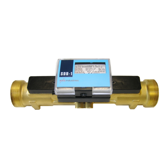
Axis Industries SDU-1M Teknik Açıklama, Kullanım Talimatları - Sayfa 6
Aksesuarlar Axis Industries SDU-1M için çevrimiçi göz atın veya pdf Teknik Açıklama, Kullanım Talimatları indirin. Axis Industries SDU-1M 12 sayfaları. Ultrasonic flow sensor

The following flow sensor sealing is provided:
5.1.
Manufacturer seals:
-
Adhesive seal-sticker on the bolts of cover protecting ultrasonic transducers (Appendix A,
Figures A1,A2 and A3).
-
Hanged seal on ultrasonic transducers mounted in flow sensor (Appendix A, Figures A4).
5.2.
Calibration seal:
-
Seal on the inner cover inside electronic box (Appendix B1).
5.3.
Mounting seal:
-
Seal on the bolt on top cover of the electronic box (Appendix A).
6.1.
Risk factors during the flowmeter installation and service is a heat conveying fluid flowing
within flow sensor with inner pressure up to 1,6 MPa and temperature up to 130
risk the service and installation works must be performed by qualified staff. Mounting of the
flowmeter is permissible only after ensuring of absence of heat conveying fluid in the pipeline.
6.2.
By connecting the flow sensor to the external pulse registration device which is powered via
AC 230V check the proper grounding of external device.
7.1.
The dimensions of the flow sensor and its connection flanges are presented in appendix A. The
wiring of signal cables is presented in appendixes B.
7.2.
Check installation of the flow sensor corresponds to the notes on the label (Flow sensor placed
in forward or return line).
7.3.
It is necessary to rinse out the flow sensor installation place in pipeline before installing the
flow sensor. It is recommended to use any piece of pipe as a substitute for the flow sensor during pipe
installation and rinsing out.
7.4.
Flow sensor meets requirements of mechanical class M1 (minimal vibrations, fixed mounting
place). Avoid mounting of flow sensor near the sources of possible vibration (pumps, etc.).
7.5. Requirements for flow sensor installation in pipeline:
- For flow sensors with threaded end connection G1 1/4 (q
requirements for straight pipeline length in upstream and down stream directions.
- For flow sensors with threaded end G2 (qp = 10 m3/h) and flanged connection
DN50...DN100 (qp = 15,0 m3/h.... 60,0 m3/h):
- upstream straight pipeline length must be not less 5DN and downstream straight
pipeline length must be not less 3DN when flow disturbance is pipe elbow (1 or 2
elbows);
- upstream straight pipeline length must be not less 10DN and downstream straight
pipeline length must be not less 3DN when flow disturbance is valve, pump or other;
7.6.
Avoid the flow sensor installation near after the pumps which can cause cavitations.
7.7.
Flowmeter can be mounted both vertically and horizontally in pipelines. Vertically mounting of
the flowmeter is allowed only if flow direction in the pipeline is from down to up.
7.8.
The direction of the sensor installation (is indicated with the arrow on the label of flow sensor)
must mach with the flow direction in pipeline.
7.9.
When flow sensor is mounted in horizontal pipeline, it is recommended to turn electronics box
on the one side of flow sensor as shown in (Fig. 1 b,c,d):
- for flow sensors with q
- if there is a possibility of the increase of fluid temperature above 100
- flow sensors with q
transducers (Fig 1 d).
PESDU1M02 (MID)
5. SEALING
6. SAFETY
7. INSTALLATION
3
= 3,5 ... 15,0 m
/h;
p
3
= 25,0...60,0 m
/h should be turned in downward position of ultrasonic
p
0
C. To eliminate this
3
= 3,5 m
/h and 6,0 m
p
0
C;
3
/h): no
6
