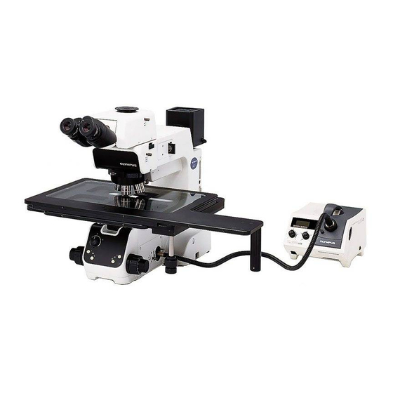
Olympus MX61 Montaj Kılavuzu - Sayfa 22
Mikroskop Olympus MX61 için çevrimiçi göz atın veya pdf Montaj Kılavuzu indirin. Olympus MX61 49 sayfaları. 200mm/300mm compatible semiconductor/fpd inspection microscopes

³
²
³
19
@
|
Fig. 26
@
Fig. 27
...
²
Fig. 28
|
ƒ
Fig. 29
Attaching the Breath Shield
12
(MX-BSH or MX-BSH-ESD)
1. Attach the two breath shield mounting brackets @ on the breath
shield ² using the provided screws (shorter ones). For the present,
tighten the screws temporarily using the Allen screwdriver. (If they
are attached completely, it becomes impossible to attach the breath
shield to the microscope frame.)
2. Align the attaching holes | on the mounting brackets with the breath
shield screw holes ³ on the microscope, and clamp using the provided
screws (longer ones).
3. Now tighten the screws that have been secured temporarily in step 1 above.
# Do not tighten the screws excessively to prevent the breath shield
from cracking.
13
Connecting the Power Cord
!Cables and cords are vulnerable to bend or twist. Do not apply
excessive force to them.
!Make sure that the main switch @ is set to "
connecting cords and cables. (Fig. 27)
!Always use the power cord provided by Olympus. If no power cord is
provided, please select the power cord by referring to the section "PROPER
SELECTION OF THE POWER SUPPLY CORD" at the end of this instruction
manual. If the proper power cord is not used, Olympus can no longer
warrant the electrical safety performance of the equipment.
1. Connect the power cord plug ² to the AC receptacle ³. (Fig. 28)
!Connect the provided power cord correctly and ensure that the
grounding terminal of the power supply and that of the 3-conductor
wall outlet are properly connected. If the equipment is not grounded/
earthed, Olympus can no longer warrant the electrical safety perfor-
mance of the equipment.
2. Connect the power cord plug | to a 3-conductor power outlet ƒ.
Fuse Replacement
1. Always set the main switch @ to "
cord before replacing fuses.
2. When the power cord plug is disconnected from the receptacle on the
microscope frame, the fuse cassette ... becomes visible. (Fig. 28).
3. Apply a flat-blade screwdriver in turn to the claws on both sides of the
fuse cassette to pull the fuse cassette outward.
4. Replace the two fuses and return the fuse cassette to its original position.
Applicable Fuses :
!Use of improper fuse type could result in a fire.
(Fig. 26)
(Figs. 27 to 29)
" (OFF) before
" (OFF) and disconnect the power
T3.15A(H)250V
(LITTELFUSE 2153.15)
(Fig. 29)
