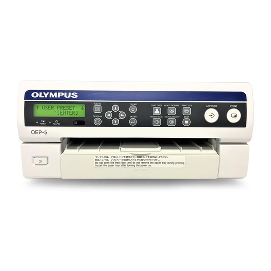
Olympus OEP-5 Talimatlar Kılavuzu - Sayfa 23
Tıbbi Ekipman Olympus OEP-5 için çevrimiçi göz atın veya pdf Talimatlar Kılavuzu indirin. Olympus OEP-5 40 sayfaları. Color video printer

3.6 Inspection of the Monitor Display
The monitor displays information and messages
according to the conditions of this instrument.
Inspection of the output image
1
Turn the color video printer (OEP-5) ON as
described in "3.1 Inspection of the Power Supply"
on page 14.
2
Display the output image from the color video
printer (OEP-5) on the monitor.
Message display 1
This field shows less urgent
messages that may be
displayed during normal use.
Print layout display
This field shows "ZOOM" except
when "ZOOM PART" is set to
"OFF" in "ZOOM MODE."
Caption display
This field shows "CAPTION"
when the printed picture is set to
contain a comment (caption).
White frame display
It is displayed in the case of a
printed picture with a white
frame.
Print quantity display
This field shows the number of
prints. It blinks during printing.
Memory page display
This field shows the selected
memory page. The memory
page number blinks during
printing or when it is reserved for
printing.
CAUTION
If messages are displayed in message display 1 or 2,
refer to "Countermeasures Against Messages" in "7.1
Troubleshooting Guide" in "INSTRUCTIONS
(ADVANCED)."
3
When the color video printer (OEP-5) is connected
to a video system center, display the image from the
color video printer (OEP-5) on the monitor by
referring to the instruction manuals for the video
system center and monitor.
4
Confirm that the monitor first displays the startup
message, and then shows the display as shown in
Figure 3.19. For details of each item, refer to
"INSTRUCTIONS (ADVANCED)."
Operation mode display
This field shows the operation mode of this
instrument. The symbol on the left shows how the
screen is split for displaying the multi-picture images
to be printed. The number on the right shows the
location where the pointer is now means that this is
the image to be printed next.
Display
Number of multi-picture images
1
2
3
4
Figure 3.19
Message display 2
This field shows more urgent
message.
Remaining ink ribbon display
This field shows the remaining
ink ribbon quantity.
Pointers
These indicate the locations
where the images are stored.
They can be moved using the
cursor keys ("v" "V" "b" "B").
The green blinking pointer
indicates the location where the
image is stored next. The
pointers are not displayed on the
monitor when the number of
multi-picture images is set to "1."
Source/Memory display
This field shows "S" when the
source image is displayed on the
monitor, and shows "M" when
the memory image is displayed
on the monitor.
3.6 Inspection of the Monitor Display
3
23
