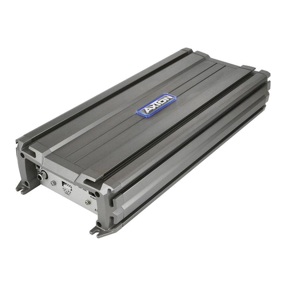
AXTON A480 Kurulum ve Kullanım Kılavuzu - Sayfa 5
Amplifikatör AXTON A480 için çevrimiçi göz atın veya pdf Kurulum ve Kullanım Kılavuzu indirin. AXTON A480 20 sayfaları. Car audio system 1-/2-/4-channel power amplifiers

1. CONNECTIONS + CONTROLS A480
1.1 CONTROLS
1
RCA INPUTS 1/2-CH
Low-level stereo RCA signal input 1/2-CH for connection to head-unit.
2
INPUT GAIN CONTROL 1/2-CH
Input gain potentiometer for channel 1/2-CH, to match the output voltage of the head-
unit to the amplifier's input.
3
HIGH INPUT 1/2-CH
Molex connector terminal to insert the High level adapter (4-pin) that picks up the
amplified speaker signal from the head unit's front output (if head unit does not feature
dedicated RCA line outs).
4
OPERATION MODE SWITCH 1/2-CH
Slide switch to select the operation mode of the X-over for section 1/2-CH of the amplifier.
5
X-OVER FREQUENCY CONTROL 1/2-CH
Control potentiometer to adjust the highpass or lowpass filtering frequency for section
1/2-CH of the amplifier.
6
RCA INPUTS 3/4-CH
Low-level stereo RCA signal input 3/4-CH for connection to head-unit.
7
INPUT GAIN CONTROL 3/4-CH
Input gain potentiometer for channel 3/4-CH, to match the output voltage of the head-
unit to the amplifier's input.
8
HIGH INPUT 3/4-CH
Molex connector terminal to insert the High level adapter (4-pin) that picks up the
amplified speaker signal from the head unit's rear output (if head unit does not feature
dedicated RCA line outs).
9
OPERATION MODE SWITCH 3/4-CH
Slide switch to select the operation mode of the X-over for section 3/4-CH of the amplifier.
10 X-OVER FREQUENCY CONTROL 3/4-CH
Control potentiometer to adjust the highpass or lowpass filtering frequency for section
3/4-CH of the amplifier.
1.2 INPUTS + OUTPUTS
11 POWER LED
LED to show "operating" status of the amplifier by green/red illumination. Green is
normal working state, red is protect state of amplifier.
12 "GND" POWER INPUT TERMINAL
Terminal to connect the amplifier to the chassis ground or negative pole of the car battery.
13 "REM" INPUT TERMINAL
Terminal to connect the amplifier to the automatic (remote) turn-on / turn-off lead of the
head unit.
– 8 –
1. CONNECTIONS + CONTROLS A480
14 "+12 V" POWER INPUT TERMINAL
Terminal to connect the amplifier to the positive +12V pole of the car battery.
15 SPEAKER OUTPUT TERMINAL
Output terminal to connect the speakers to the amplifier in either stereo or bridged
mode.
1
bm bn
2
3
4 5
7
8
9 bl
bo bp
bq
– 9 –
6
