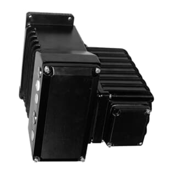
ABB EBN861 Talimatlar Kılavuzu - Sayfa 8
Kontrolör ABB EBN861 için çevrimiçi göz atın veya pdf Talimatlar Kılavuzu indirin. ABB EBN861 17 sayfaları. Power electronic units for field installation. for the control of contrac actuators of the pme, lme, rhd or rsd series
Ayrıca ABB EBN861 için: Talimatlar (18 sayfalar)

7.5.1
External fuses for EBN861
Apart from the internal fuses (see also 7.5), the EBN861 power electronic unit requires two additional
external fuses, which are supplied separately to the unit.
AC 230 V 1~
Fig. 5:
External fuses
Fig. 6:
External fuse; 35 A
8.
Mounting
Install the electronics close to the actuator. The connection is made via a 24-pin connector (additional
10-pin connector if heater is used) on the actuator side and screw terminals on the electronics side. The
electronics are provided with the appropriate metric cable holes (see Figures 1 to 3 for the assignment).
8.1
Preparing the electronics
- Make sure that disconnection on site is possible.
- Shield all signal cables and the motor cable between the actuator and the electronics
- The shield of the connection cable between the electronics and the actuator must be applied to both
housings.
8.2
Mounting of EAN823 / EBN853
Disconnect the electronics and the actuator prior to all installation and service works.
- Fasten the unit to the vertical mounting plate, using screws of property class 8.8 (tensile strength
800 N/mm
- Make sure that there is enough spacing for mounting, and that the unit can be easily accessed
- Make sure that the cable holes are oriented to the left
- Remove the cover of the connection chamber (2)
- Insert the cables through the cable glands and connect them according to the wiring diagram.
- Use appropriate cable glands to ensure a water-tight installation
- Check if the cable is connected properly; then close the connection chamber cover.
Adjust as described in section 9.
8.3
Mounting of EBN861
Electronics unit EBN861 has a total weight of around 42 kg. For safety reasons it may be necessary to
mount each of the two parts separately.
- Undo and remove the cover screws.
- Fold down the front part, then lift it off from the hinge bolts towards the top.
- Undo the internal connection between the two housing parts.
- Undo the hinge screw
- First mount the rear part of the housing
- Attach the front housing part to the hinge bolts, insert a screw into the top bolt and fasten.
- Make the internal connections between the two housing parts.
- Close the cover and fasten the cover screws
- Connect the cables
8
35 A
16 A (
2
; yield strength 640 N/mm
ϑ
)
Fig. 7:
External thermal fuse; 16 A
2
)
L
Electronic
unit
N
PE
