CIRCUIT DESIGN MU4-USBIF Kullanım Kılavuzu - Sayfa 13
USB Arayüzleri CIRCUIT DESIGN MU4-USBIF için çevrimiçi göz atın veya pdf Kullanım Kılavuzu indirin. CIRCUIT DESIGN MU4-USBIF 18 sayfaları. Embedded low power radio modem usb interface board
Chapter 4 How to Design a User System
When embedding theMU4-USB (MU-4 + MU4-USBIF) in a user system, pay due attention to the design of the board
and case.
This board is connected to a PC provided with a USB port. Connect the unit to the PC with the dedicated USB cable
provided. Power for the product is supplied from the PC through the USB cable.
If you house the product in a case, determine the position of the ground and antenna through a variety of tests.
In addition, if you attach LEDs to the case, connect them with inch-pitch through holes with reference to the diagram
below.
If you use a USB cable other than the one provided, use a double shield cable (USB 2.0 High Speed). Otherwise,
radio waves may not be emitted due to high frequency noise from the USB.
When using USB, pay attention to the total current capacity of the other equipment since it can result in malfunctions.
When marketing products that use this product, provide information about the current in your operation guide.
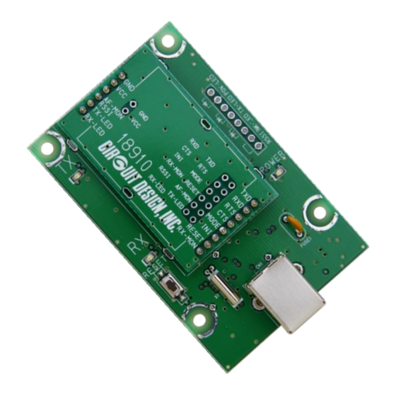
◼ 4.1.1 Controlling the MU4-USB with a PC
MU4-USB
*1
*1
OG_MU4-USBIF_v10e
4.1 Embedding the Product
λ/4 lead antenna *2
MU-4
Inch pitch through holes only.
If necessary, mount an 8-pin
socket, and attach external LEDs
etc.
USB-B receptacle
User PC
Power LED
*1
GND
Tx LED
Rx LED
Connecting external LEDs
・To prevent noise, attach a ceramic
*1
capacitor of about 100 pF to the LED.
・Terminals 1, 3, and 5 there are 1kΩ
resistors in the MU4-USB.
*1: Solder the terminal lug etc. and connect it to the user case
ground. Determine the connection point with various tests.
*2: If the antenna is bent to fit inside, the communication
range falls and communication errors become frequent. Do
Not put the antenna inside a metal case.
12
OPERATION GUIDE
100pF
1
2
3
+3v
4
100pF
5
+3v
6
100pF
RSSI
7
}
To the
processing circuit
GND
8
Circuit Design, Inc.