Digikeijs DR4088GND Kullanım Kılavuzu - Sayfa 9
Kontrol Ünitesi Digikeijs DR4088GND için çevrimiçi göz atın veya pdf Kullanım Kılavuzu indirin. Digikeijs DR4088GND 15 sayfaları. Feedback module
Ayrıca Digikeijs DR4088GND için: Kullanım Kılavuzu (11 sayfalar), Manuel (8 sayfalar), Kullanım Kılavuzu (12 sayfalar)

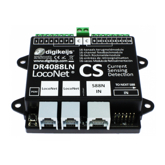
DR4088LN-CS / GND / OPTO
3.2.2 Programming with any control panel or app.
1.
Connect the central unit to the DR4088LN-xx to be programmed
(normally it is not necessary to disconnect other feedback modules from the LocoNet®).
2.
First, the DR4088LN-xx must be assigned the start address.
Open the turnout control panel that contains the desired start address that the DR4088LN-xx is to receive. Depending on which control panel, handset or app
is used for programming, either the corresponding turnout or the corresponding turnout control panel must be called at the control panel. With some App's a
corresponding switch with the desired address must be created.
3.
Press the programming button on the DR4088LN-xx. The green LED starts flashing to indicate that the DR4088LN-xx is in programming mode.
4.
To assign the start address switch the switch address e.g. 1 once (so only red or green!).
5.
The green LED on the DR4088LN-xx now flashes in a different clock pulse and signals that the DR4088LN-xx next expects the number of feedbacks. The num-
ber of feedback signals is again sent to the DR4088LN-xx via a switch command.
Example:
DR4088LN-xx
DR4088
Start address 1
Number of feedback units 32
DR4088LN-xx
2x DR4088
Start address 1
Number of feedback units 48The
DR4088LN-xx
3x DR4088
Start address 1
Number of feedback sensors 64
etc.
6.
At the control panel, at the handset controller or in the app, call up the turnout control panel which contains the address corresponding to the number of
feedbacks.
With some App's a corresponding switch with the desired address must be created. Again, only red or green switching applies.
7.
The DR4088LN-xx automatically terminates the programming mode and is now programmed with the start address and the number of feedback devices.
Attention! At the S88 connection of the DR4088LN-xx A maximum of 15 DR4088 can be connected to the S88 connection of the DR4088LN-xx. This results
in a maximum number of 256 feedback contacts that a DDR4088LN-xx can manage.
Example: DR4088LN-xx
www.digikeijs.com
® R-Bus, B-Bus are trademarks which are registered in the name of Modelleisenbahn GmbH. XpressNet and RS-Bus is a trademark registered in the name of Lenz
2021-04-21
The switch address 32 must be sent here.
The switch address 48 must be sent here.
The switch address 64 must be sent here.
15x DR4088
Start address 1
Occupied feedback device Address range 1 - 256
P 9
