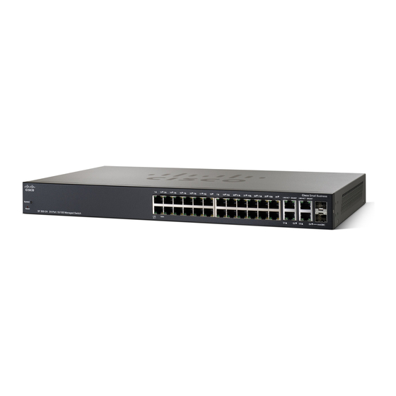
Cisco 300 Series Hızlı Başlangıç Kılavuzu - Sayfa 4
Anahtar Cisco 300 Series için çevrimiçi göz atın veya pdf Hızlı Başlangıç Kılavuzu indirin. Cisco 300 Series 18 sayfaları. Managed switches
Ayrıca Cisco 300 Series için: Veri Sayfası (14 sayfalar), Hızlı Başlangıç Kılavuzu (17 sayfalar), Hızlı Başlangıç Kılavuzu (17 sayfalar)

- 1. Quick Start Guide
- 2. Mounting the Cisco Switch
- 3. Rack-Mount Placement
- 4. Wall Mounting
- 5. Connecting Network Devices
- 6. Power over Ethernet (Poe) Considerations
- 7. Troubleshoot Your Connection
- 8. Front Panel Ports
- 9. Reset Button
- 10. Back Panel
- 11. Front Panel Leds
- 12. Returning the Device to the Factory Default Settings
- 13. Where to Go from here
Rack-Mount Placement
Remove the four screws from each side near the front of the switch.
S
1
TEP
Retain the screws for re-installation. (Do not remove the four screws
from each side near the back of the switch.)
Place one of the supplied spacers on the side of the switch so the
S
2
TEP
four holes of the spacers align to the screw holes. Place a rack
mount bracket next to the spacer and reinstall the four screws
removed in
If your screws are not long enough to reattach the bracket
N
OTE
with the spacer in place, attach the bracket directly to the case
without the spacer.
Repeat
S
3
TEP
After the mounting hardware has been securely attached, the
S
4
TEP
switch is now ready to be installed into a standard 19-inch rack.
For stability, load the rack from the bottom to the top, with the
C
AUTION
heaviest devices on the bottom. A top-heavy rack is likely to
be unstable and may tip over.
Wall Mounting
Only the 8-port models of the switch can be wall-mounted.
The switch should be mounted so that the ports face up or down.
N
OTE
Do not mount the switch with the ports to the side.
4
Step
1.
Step 2
for the other side of the switch.
Cisco 300 Series Managed Switches
