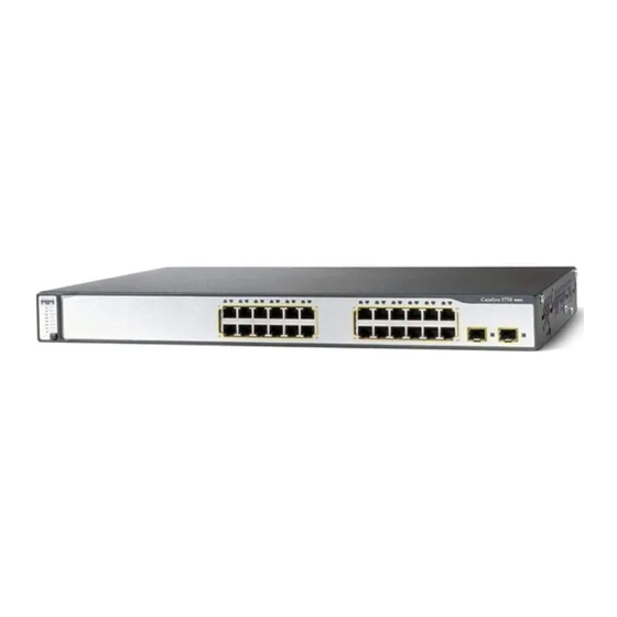
Cisco 3750G - Catalyst Integrated Wireless LAN Controller Başlangıç Kılavuzu - Sayfa 8
Anahtar Cisco 3750G - Catalyst Integrated Wireless LAN Controller için çevrimiçi göz atın veya pdf Başlangıç Kılavuzu indirin. Cisco 3750G - Catalyst Integrated Wireless LAN Controller 49 sayfaları. Integrated wireless lan controller switch
Ayrıca Cisco 3750G - Catalyst Integrated Wireless LAN Controller için: Yapılandırma Kılavuzu (40 sayfalar)

(Optional) You can enter the Optional Settings information now or enter it later by using
Step 14
the device manager interface:
• In the Host Name field, enter a name for the switch. The host name is limited to
31 characters; embedded spaces are not allowed.
• In the Telnet Access field, click Enable if you are going to use Telnet to manage the
switch by using the command-line interface (CLI). If you enable Telnet access, you
must enter a Telnet password.
• In the Telnet Password field, enter a password. The Telnet password can be from
1 to 25 alphanumeric characters, is case sensitive, allows embedded spaces, but does
not allow spaces at the beginning or end. In the Confirm Telnet Password field,
re-enter the Telnet password.
• In the SNMP field, click Enable to enable Simple Network Management Protocol
(SNMP). Enable SNMP only if you plan to manage switches by using
CiscoWorks 2000 or another SNMP-based network-management system.
If you enable SNMP, you must enter a community string in the SNMP Read
Community field, the SNMP Write Community field, or both. SNMP community
strings authenticate access to MIB objects. Embedded spaces are not allowed in
SNMP community strings. When you set the SNMP read community, you can access
SNMP information, but you cannot modify it. When you set the SNMP write
community, you can both access and modify SNMP information.
• In the System Contact field, enter the name of the person who is responsible for the
switch. In the System Location field, enter the wiring closet, floor, or building where
the switch is located.
Step 15
Click Submit to save your settings, or click Cancel to clear your settings.
When you click Submit, the switch is configured and exits Express Setup mode. The PC
displays a warning message and then tries to connect with the new switch IP address. If
you configured the switch with an IP address that is in a different subnet from the PC,
connectivity between the PC and the switch is lost.
Disconnect the switch from the PC, and install the switch in your network. See the
Step 16
"Managing the Switch" section on page 9 for information about configuring and
managing the switch.
If you need to rerun Express Setup, see the "Resetting the Switch" section on page 35.
8
