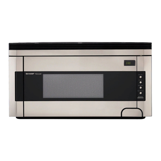
Sharp Carousel R-1512 Kurulum Talimatları Kılavuzu - Sayfa 3
Mikrodalga Fırın Sharp Carousel R-1512 için çevrimiçi göz atın veya pdf Kurulum Talimatları Kılavuzu indirin. Sharp Carousel R-1512 9 sayfaları. Over the range microwave oven
Ayrıca Sharp Carousel R-1512 için: Broşür ve Teknik Özellikler (8 sayfalar), Kurulum Talimatları Kılavuzu (40 sayfalar), Pişirme Kılavuzu (40 sayfalar), Servis Kılavuzu (32 sayfalar), Manuel (40 sayfalar)

6
INSTALLATION HARDWARE
The INSTALLATION HARDWARE items
1-7 are in a small bag. Items 8-" are
packed separately. All items are in a
small carton packed below the oven.
Figure 4
Parts shown not to
common scale.
7
PREPARATION OF THE OVEN
1. Open the bottom of the carton, bend the carton flaps
back and tilt the oven over to rest on plasticfoam
pad. Lift carton off oven and remove all packing
materials, INSTALLATION INSTRUCTIONS,
WALL TEMPLATE, TOP TEMPLATE, Turntable
and Turntable Support. DO NOT REMOVE THE
WAVEGUIDE COVER, which is located on the right
side wall of the oven cavity.
2. Check the oven for any damage, such as misaligned
or bent door, damaged door seals and sealing
surfaces, broken or loose door hinges and latches
and dents inside the cavity or on the door. If there
is any damage, do not operate the oven and
contact your dealer or SHARP AUTHORIZED
SERVICER.
3. Turn oven on the side. See Figure 5.
4. Follow steps (A)-(D) to remove mounting plate from
the back of the oven as shown in Figure 5.
(A) Release mounting plate by pulling out the lever
that is on the bottom of the oven. See Figure 6.
(B) When lever is out, pull that side of the mount-
ing plate away from the oven. See Figure 5.
(C) Repeat step (A) on other side.
(D) Repeat step (B) on other side.
ITEM
NAME
1
Wood Screw 5 X 30 mm
2
Toggle Bolt with nuts #10 - 24 X 50 mm
3
Top Cabinet Screw 5 X 60 mm
4
Power Cord Hanger
5
Tapping Screw 4 x 12 mm
6
Flat Washer 30 mm diameter
7
Grommet
8
Rear Cushion
9
Exhaust Damper Assembly
!
Scale Plate
"
Grease Filter
Figure 5
Figure 6
Use screwdriver to
assist in releasing
mounting plate.
Bottom of Microwave
3
QUANTITY
6
4
2
1
3
2
1
1
1
2
2
(A)
(C)
(A)
PART CODE
XTSSD50P35000
LX-BZ0195WRE0
XBRSD50P60000
LX-MZB001MRE0
XOTSD40P12000
XWHSD50-16300
LBSHC0040MRE0
PCUSUB059MRP0
FFTA-B003MRK0
LANG-B002MRP0
PFIL-B002MRE0
(B)
(D)
Mounting Plate
