BITRONVIDEO AV 1423/010 Kurulum Kılavuzu - Sayfa 3
TV Montajı BITRONVIDEO AV 1423/010 için çevrimiçi göz atın veya pdf Kurulum Kılavuzu indirin. BITRONVIDEO AV 1423/010 6 sayfaları. Bracket for t-line monitors
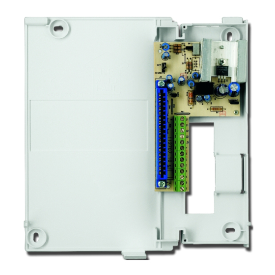
Selezione dell'impedenza di ingresso del segnale video
Il commutatore a slitta SW1, permette di selezionare l'impedenza di ingresso del segnale video. La posizione
di default L, prevede la bassa impedenza (tipicamente 75 Ω).
Ponendolo su H l'impedenza selezionata risulterà elevata (47.000 Ω).
Per mofi care la posizione di questo interruttore, ricordare che esso dipende dal tipo di impianto nel quale il
monitor verrà montato:
−
Su L in impianti con scatola di derivazione al piano SD55 (nel caso di condominio...)
−
Su L in impianti monofamiliari (installazione punto a punto).
−
Su H in impianti con pi ù di un monitor e senza scatola di derivazione al piano. Sono impianti defi niti
entra/esci, dove i fi li di collegamento del segnale video devono arrivare direttamente sui morsetti A e
B del monitor e ripartire esattamente dai medesimi morsetti verso i monitor successivi. Attenzione, in
questa confi gurazione l'ultimo monitor dovrà prevedere le resistenze di terminazione.
Segreto di conversazione
Il ponticello J1 consente di attivare od escludere il segreto di conversazione audio. Con il ponticello
posizionato su "OFF" (impostazione di default) il segreto di conversazione è escluso. Sollevando in qualsiasi
momento il microtelefono del monitor, sarà possibile conversare con il posto esterno. Con il ponticello
posizionato su "SEGRETO" il segreto di conversazione è attivo. Sarà possibile conversare con il posto esterno
soltanto dopo la ricezione di una chiamata.
ENGLISH
INSTALLATION
1.
Fix up the arrival of the cables conduit to match with the bracket cables passage. The suggested height
is from 1,48 to 1,52 meters from the fl oor (fi g.1).
2.
Fix the bracket to the wall by using the four screws provided, and match the central hole to the
prospective embedded box, previously walled-in, or with the cable left out from the wall.
3.
Connect cables to the terminal board present on the bracket.
4.
Mount the monitor on the bracket by using the upper hooks and pivoting it till blocking the monitor by
the automatic fi xing hook (fi g.2). In order to take it off from the bracket, press the hook as shown in
the picture (fi g. 2) and make the reverse movement.
CONNECTIONS
On the bracket there is a terminal board enabling the wiring of the following signals:
1:
System ground
3:
Monitor supply positive
T:
Monitor power-on input without ringer activation.
C:
Audio, call and door opener input.
P:
Floor call input
B:
Positive video input
A:
Negative video input
E:
Monitor auto-activation
Q1, Q1: NA 24V 0,5A free contact
Q2, Q2: NA 24V 0,5A free contract
LD:
Red led available on the monitor for open door signalling.
To have the monitor perfectly working, connect wires according to the schemes attached to the video unit.
1-3-A-B-C wires should be absolutely connected, in order to have a correct system operation.
4
Auxiliary connections description
All connections described here below enable some monitor auxiliary functions.
♦
The P connector will be connected if the call at fl oor is requested. In this case an A3000 (AV1142)
auxiliary power supply should be connected, in order to produce a negative call to all the riser or to an
A70 IRC (AV7362) power supply.
♦
The T connector, if connected, allows to turn on the monitor without activating the ringer. This function
is activated by providing a –12V voltage between T and 1 when there is a +20V voltage on the connector
3.
♦
The E connector, if connected, allows to turn on the monitor and the camera by pressing the button with
•
"
", presents on the monitor. The function is available only if there is not any other monitor active.
♦
Q1 and Q1 connectors enable the contact usually open, of the button "A" presents on the monitor. It
can be used as activation for staircase lights control, cameras control, electric entrances control,
etc ...
♦
Q2 and Q2 connectors enable the contact, usually open, of the button "B" presents on the monitor. It
can be used as activation for staircase lights, cameras, electric entrances, etc ...
♦
The LD connector enables the red led on the monitor. The activation of the led is obtained by
having a +12Vdc voltage referred to the system ground ("1"). It can be used as open door signalling or
by connecting it together with the connector "3", it can indicate the system busy condition and so the
impossibility to make the auto-activation. When the monitor is turn on, the same led will be green and it
will be predominant on a possible outdoor signalling. By setting the monitor in a correct way (please see
the monitor manual), and by providing a continuous supply of +12Vdc voltage to the connector LD,
it will be possible to turn on the led to signal the exclusion of call (MUTE).
Selection of video signal input impedance
The slider switch allows to select the impedance value for the video signal input. By setting such switch on
"L" the selected impedance will be low (typically, 75 Ohm), while by setting it on "H" the resulting value will
be high (47,000 Ohm). To set this switch correctly, remember it must be placed:
−
On "L" position for systems with SD55 video splitters at each fl oor (e.g. apartment buildings....) .
−
On "L" position for one-family systems (one-to-one installations)
−
On "H" position for systems with several looping monitors, without video splitter box. They are defi ned as
"entry/exit" systems where the video signal connecting wires arrive directly on A and B terminals of one
monitor and leave from the same terminals toward the next monitor. Pay attention in this confi guration
to closing resistors.
Secrecy of conversation
The jumper J1 is used to switch on or off the secrecy of conversation. Inserting the jumper on OFF (default
setting) the secrecy of conversation will not be used. In this case, lifting the monitor handset, will put the
user in communication with the outdoor station.
Inserting the jumper on "segreto" the secrecy of conversation will be activated. In this case the conversation
with the outdoor station will be possible only after receiving a call.
012175867.00
012175867.00
5