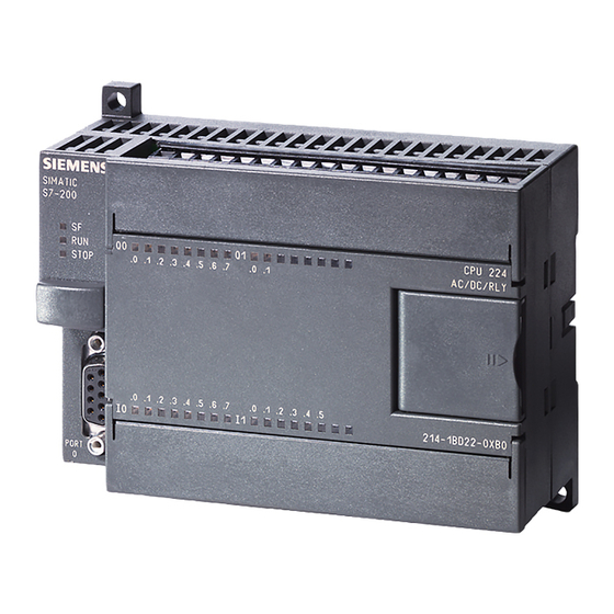
Siemens SIMATIC S7-200 Sürücü El Kitabı - Sayfa 18
Endüstriyel Ekipmanlar Siemens SIMATIC S7-200 için çevrimiçi göz atın veya pdf Sürücü El Kitabı indirin. Siemens SIMATIC S7-200 28 sayfaları. Ethernet gateway for simatic mpi/ profibus driver
Ayrıca Siemens SIMATIC S7-200 için: Manuel (30 sayfalar), Manuel (35 sayfalar), Manuel (49 sayfalar), Manuel (18 sayfalar), Sistem Kılavuzu (20 sayfalar)

Siemens S7-200 Driver
Address Type
Timer Current Values
Timer Status Bits
Counter Current
Values
Counter Status Bits
High Speed Counters
Analog Inputs
Analog Outputs
*For Timer and Counter status bits, dot bit notation is not used. The status bit for timer 7 would be T7
declared as Boolean.
**For Analog Inputs and Outputs, the address must be even (AI0, AI2, AI4...). Analog Outputs (AQ) are Write
Only: there is no method for reading the value of Analog Outputs from the device. Write-only data types of
this driver return the last value written when read if an initial write to device has completed. If an initial write
has not completed, the driver returns a value of 0 when read. This only applies while a client is connected to
the server.
The actual number of addresses of each type depends on the Siemens S7-200 device in use. Each type does
not necessarily support an address of 0 to 65535. For address ranges, refer to the device's documentation.
Optional Dot Bits
For Byte, Word, Short, DWord or Long data types, an optional .bb (dot bit) can be appended to the address to
reference a bit in a particular value. The valid ranges for the optional bit is 0-7 for Byte types; 0-15 for Word,
Short, and Boolean types; 0-31 for DWord and Long types; and 1-211 for String types. Float types do not
support bit operations. Boolean and String types require a bit number. The bit number for String types
specifies the number of characters in the string.
Dynamic addresses with bit numbers in the range of 0-7 default to Byte; 8-15 default to Word; 16-31 defaults
to DWord. V Memory addresses with a bit number larger than 31 defaults to String. The following diagram
illustrates how the driver maps bits within the controller.
Range
V00000-V65532
V00000.bb-V65535.bb
V00000.bb-V65534.bb
V00000.bb-V65532.bb
T00000-T65535
T00000-T65535
C00000-C65535
C00000-C65535
HC00000-HC65535
AI00000-AI65534**
AQ00000-AQ65534**
www. ptc.com
Type
DWord, Long, Float,
String
Byte
Boolean, Word, Short
DWord, Long, String
DWord, Long
Boolean*
Word, Short
Boolean*
DWord, Long
Word, Short
Word, Short
Access
Read/Write
Read Only
Read/Write
Read Only
Read Only
Read Only
Write Only
18
