Siemens SINAMICS G120P Manuel - Sayfa 8

Endüstriyel Ekipmanlar Siemens SINAMICS G120P için çevrimiçi göz atın veya pdf Manuel indirin. Siemens SINAMICS G120P 18 sayfaları. Line reactors for power modules pm330
Ayrıca Siemens SINAMICS G120P için: Kullanım Talimatları Kılavuzu (28 sayfalar), Kullanım Talimatları Kılavuzu (26 sayfalar), Kullanım Talimatları Kılavuzu (34 sayfalar), Kullanım Talimatları Kılavuzu (24 sayfalar), Kullanım Talimatları Kılavuzu (22 sayfalar), Kullanım Talimatları Kılavuzu (26 sayfalar), Kullanım Talimatları Kılavuzu (22 sayfalar), Kullanım Talimatları Kılavuzu (22 sayfalar), Kullanım Talimatları Kılavuzu (18 sayfalar)
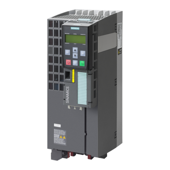
Siemens SINAMICS G120P Manuel
2 Engineering
Key
QB
OK
OFF
MANUAL/
AUTO
ON
Plug the Basic Operator Panel BOP-2 into the inverter.
To connect the Basic Operator Panel BOP-2 to the inverter, proceed as follows:
Table 2-2: Plug BOP-2 into inverter
Step
1.
2.
3.
Pump with SINAMICS G120P
Entry-ID: 109759888,
V1.0.1,
When navigating through a menu, the available screens are scrolled by
pressing the down key.
When changing a parameter value, the displayed value is reduced by
pressing the key.
When navigating through the menus, pressing the OK button confirms the
selection of a menu command.
When working with parameters, pressing the OK key allows the parameter to
be changed. Pressing the OK button again confirms the entered value and
the previous screen is displayed again.
In the error screen, the key is used to clear errors.
In AUTO mode, pressing the OFF button has no effect and is ignored.
If the key is pressed for more than 2 seconds, the inverter will execute the
OFF2 command and the motor will coast to a standstill.
Pressing the MANUAL/AUTO key while MANUAL mode is active switches the
inverter to AUTO mode and disables the ON and OFF keys.
Pressing the MANUAL/AUTO key while the AUTO mode is active switches
the inverter to MANUAL mode and the ON and OFF keys are activated.
The ON key is not active in the AUTO operating mode. Pressing this key is
ignored.
The inverter is started in MANUAL mode. The symbol for the running drive is
displayed on the inverter.
Remove the inverter dummy cover.
Insert the bottom edge of the BOP-2 enclosure into the appropriate recess in the
inverter enclosure.
Press the BOP-2 on the inverter until the BOP-2 clicks audibly into place on the
inverter housing.
09/2019
Function
Description
8