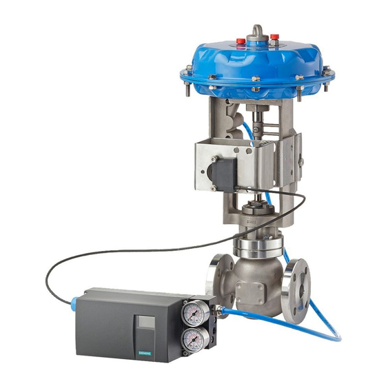
Note
Observe the height
Adjust the height of the NCS assembly kit so that the lever position is in line horizontally with the stroke center. Use the
lever scale on the actuator for orientation. If a symmetrical assembly is not possible, you must always ensure that the
lever is in horizontal position within the range of the stroke.
Reference
For information on the scope of delivery, refer to chapter "Scope of delivery of NCS for linear actuators > 14 mm (0.55 inch) .
(Page 34)".
5
Wiring
5.1
Incorrect mounting
CAUTION
Incorrect mounting
The device can be damaged, destroyed or its functionality impaired through improper mounting.
● Before installing ensure there is no visible damage present on the device.
● Make sure that process connectors are clean, and suitable gaskets and glands are used.
● Mount the device using suitable tools. Refer to the information in "Technical data" , for example installation torques
requirements.
5.2
Unsuitable cables and/or cable glands
WARNING
Unsuitable cables and/or cable glands
Danger of explosion in hazardous areas.
● Only use suitable cables and cable glands complying with the requirements specified in "Technical data".
● Tighten the cable glands in accordance with the torques specified in "Technical data".
● When replacing cable glands use only cable glands of the same type.
● After installation check that the cables are seated firmly.
Prerequisites
You need the EMC filter module with order number C73451-A430-D23 to connect the NTC to the positioner. The positioner
supplies auxiliary power to the NTC via the EMC filter module.
For installation and wiring instructions for the EMC filter module, refer to the positioner operating instructions, chapter
"Installation/Mounting" and to chapter "Wiring".
28
SIPART PS2 Non-Contacting Sensor (NCS)
A5E00097485-07, 01/2012

