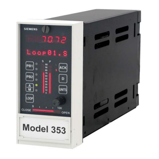
Siemens 353 Kullanıcı Kılavuzu - Sayfa 13
Kontrolör Siemens 353 için çevrimiçi göz atın veya pdf Kullanıcı Kılavuzu indirin. Siemens 353 20 sayfaları. Multi-purpose training panel
Ayrıca Siemens 353 için: Kullanıcı Kılavuzu (4 sayfalar)

UM353TP-1
2.4 ELECTRICAL POWER INPUT
Unless otherwise specified at the time of purchase, the Training Panel has an electrical cord with a standard three-
prong ground plug for 120/240 Vac service. To determine the correct electrical power input for a controller, perform
the following steps. Refer to the "Maintenance" section of the Model 353 User's Manual (UM353-1) for specific
information on assembly installation and adding of option boards.
1.
Disconnect the Training Panel from all sources of external power to eliminate a potential electrical shock
hazard.
2.
Fasten a conductive wrist strap on your wrist and ground the strap to a properly grounded static dissipative work
mat or other good ground.
3.
Get the MPU Controller board that is to be installed. Determine whether the board is for 120/240 Vac or 24 Vdc
power input. First, locate the rectangular part number label on the circuit board. Then, note the part number and
refer to the following table.
120/240 Vac MPU Controller Boards
•
If the MPU Controller board accepts 120/240 Vac, proceed to Section 2.5 Assembly Installation.
•
If the MPU Controller board accepts 24 Vdc, go to step 4 below.
4.
To convert the Training Panel to accept a 24 Vdc MPU Controller board and to operate from a 24 Vdc source:
1) Remove the wiring channel cover from the case.
•
Training Panels with Case Option 2 - The cover is secured by a screw in the rubber foot at the bottom
of the case.
•
Training Panels with Case Option 4 - The cover is secured by a screw at the top of the case and a screw
in the rubber foot at the bottom of the case.
2) Slide the wiring channel cover straight back from the front panel while feeding the power cable into the
opening in the channel cover. The plastic terminal cover may detach; it will be reinstalled later.
3) Refer to the Installation section of UM353-1, Rev. 9 or higher, and remove the terminal cover.
4) Disconnect the supplied AC power cable. Pull the cable out of the channel cover.
5) Again, refer to the Installation section of UM353-1, Rev. 9 or higher, for DC+, DC-, and ground
connections to the case terminals. Route the wires through the opening in the channel cover and make the
connections at the H (DC+) and N (DC-), terminals and the green ground screw.
6) Label the unterminated end of each wire to indicate the correct connection to the 24 Vdc power source.
7) Install the terminal cover. Slide the wiring channel cover onto the case while pulling out any excess 24 Vdc
power wire. Be sure the grommet remains seated in the hole in the terminal cover. Reinstall the screw(s)
removed in step 1).
8) Go to Section 2.5 Assembly Installation.
April 2002
16276-91
16276-111
16276-131
24 Vdc MPU Controller Boards
16276-101
16276-121
16276-141
Installation
2-3
