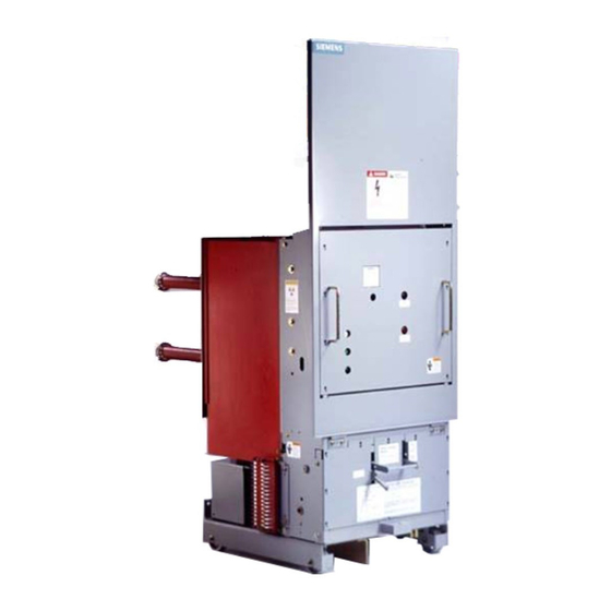
Siemens 15-FSV-750 Kurulum Operasyon ve Bakım - Sayfa 15
Anahtar Siemens 15-FSV-750 için çevrimiçi göz atın veya pdf Kurulum Operasyon ve Bakım indirin. Siemens 15-FSV-750 48 sayfaları. Vacuum circuit breakers fsv series and msv series

Technical Data
Service Conditions
The fol lowing parameters define the u sual service conditions
under which the ci rcuit breakers shall be considered su itable
for operating at their standard ratings. Conditions of use be
yond these l i mits m u st be g iven special consideration, con
sultation with the factory or reference to the IEEE Application
Guide, ANSI C37 010
Maximu m Ambient Tem perat u re
Minimu m Ambient Temperature
Altitude
Unusual service conditions which expose the equipment to
d ust, steam, salt s pray, corrosive gases, d ripping water, vibra
tion, shocks , high and low temperatu res, high altitudes and the
like may req u i re special construction. Refer concerns to the
factory.
The values of insulation level compiled above are referred to
sea level in accordance with ANSI C37. 04-1979 consolidated
standards . The higher the site altitude, the lower the insu lating
capacity of the air. The decrease i n insulating capacity is ne
g lected by standards for altitudes of up to 3 ,300 ft. ( 1 000m)
above sea level. For hig her altitudes, the values of low-fre
quency withstand voltage, impulse withstand voltage and rated
continuous cu rrent must be corrected in accordance with ta
ble 2 .
Table 2
Altitude Correction Factors,
Altitude
Rated Maximum
Voltage and
ft.
(m)
Insulation Level
( 1 000)
1 . 00
3300
5000
( 1 500)
0.95
1 0000 . (3000)
0.80
NOTE: Interpolated correction factors shall be used in
determining factors for intermediate altitudes.
40 C (104 F)
-30 C ( -22 F)
1 000 meters (3300 Feet)
k
Rated Continuous
Current
1 . 00
0 . 99
0.96
General Performance Data
Operating Times - Typical Values
Characteristic
Cycles (60 Hz)
Closing Time
Opening Time
Arcing Time at 60Hz
I nterrupting Time
General Performance Data
Typical Closing and Tripping Solenoid Characteristics
Control Voltages
Close Coil
ANSI C37.06 Tbl. 10
Ohms
48 VDC
23
121
125 VDC
250 VDC
487
120 VAC 60Hz
1 2 1
240 VAC 60
487
General Performance Data
Typical Spring Charging Motor Characteristics
Control Voltages
ANSI C37.06 T bl. 1 0
48 VDC
1 25 VDC
250 VDC
120 VAC 60Hz
240 VAC 60Hz
General Performance Data
Auxiliary Switch Ratings
Characteristic
Maxim u m Operating Voltage
Contin uous C u rrent, Max.
Making C u rrent, Max.
Breaking Capacity
Resistive Load D C or AC
I n ductive Load at 220VD C
(LIR
20ms)
=
Page 10
MS
4 . 5
75
2.0
33
0.9
15
50
5
Trip Coil
Amps
Amps
Ohms
2. 1
2.4
20.0
1 . 0
23
5.4
0 . 5
121
2.1
0.9
23
4.7
0.4
121
1.8
Current
Charge Time
Amps
Seconds
8
10
4
10
2
10
6
10
3
10
Rating
v
500
10 A
30 A
1200 VA
750 VA
