Siemens 3TM Kullanım Talimatları Kılavuzu - Sayfa 17
Anahtar Siemens 3TM için çevrimiçi göz atın veya pdf Kullanım Talimatları Kılavuzu indirin. Siemens 3TM 48 sayfaları. 1-pole vacuum contactor 4.15 kv - 6.9 kv
Electromagnetic unlatch-
ing and manual unlatching
Subsequent ordering
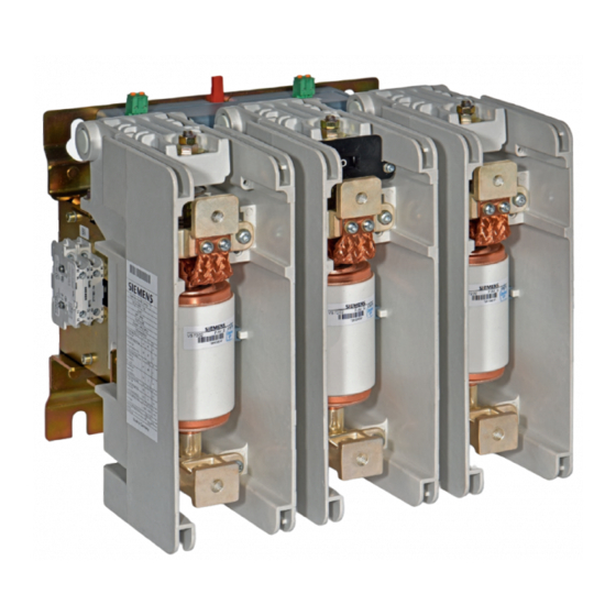
Vacuum contactor, 1-pole
IEC 62271-106
3TM1...
S.3TM../00000001
Rated voltage
Rated lightning impulse
withstand voltage
Rated short-duration
power frequency withstand
voltage
Rated frequency
Rated switching current
AC-1 to AC-4
Thermal current
Rated short-circuit break-
ing current
M1
Additional closing delay
Additional opening delay
Y1
Set-up height above sea
level
Mechanical stress
Weight
Date of manufacture
Made in Germany
Fig. 9
Example - rating plate for vacuum
contactor 3TM
9229 0098 176 0-
2019-01-09
Unlatching is done via:
•
Electromagnetic unlatching, remote-controlled
•
Manual unlatching via push rod or draw bar.
The remote tripping is carried out via the electromagnetic shunt release Y1 (9). If
manual unlatching (EMERGENCY STOP) via the push rod or draw bar is not avail-
able, the shunt release Y1 can be carefully manually actuated from the rear side of
the vacuum contactor in a de-energised state and for test purposes (see details in
Fig. 8).
Manually operated unlatching (EMERGENCY STOP) is performed with a push rod
or draw bar (12, 15) with approx. 30 N. The customer is to mount M4 threaded rods
for the push rod or draw bar with fitting end pieces or other suitable terminators.
Tightening torque 3 ±0.5 Nm.
If no latching or unlatching is available but is planned for backfit, the following mod-
ules can be subsequently ordered and mounted:
•
Mechanical closing latching with shunt release Y1
•
Manually operated unlatching mechanical system (EMERGENCY STOP) with
draw bar or push rod
See chapter "Mounting the mechanical closing latching (optional) and manual
unlatching (optional)", p. 29.
A description of the installation is only supplied with the operating instructions of the
retrofit kit.
Rating plate
a
b
c
d
e
f
g
h
i
k
Ur
... kV
l
Up ... kV
m
Ud ... kV
n
fr
... Hz
o
Ie
... A
p
Ith
... kA
r
Isc ... kA
s
Ua ... V
t
tc
... ms
u
to
... ms
v
U
... V
-1250 to
w
m
+2000
x
...
y
16
kg
z
08/18
a Manufacturer
b Type designation
c Classification according to the IEC standard
d Classification according to further standard
e Classification according to further standard
f
Line without entry
g MLFB, as on the order
h Special versions and additional equipment
i
Factory number, as on the order
k Rated voltage U
r
l
Rated lightning impulse withstand voltage U
m Rated short-duration power frequency withstand
voltage U
d
n Rated frequency f
r
o Rated switching current I
AC-1 to AC-4
p Thermal current I
th
r
Rated short-duration breaking current I
s Rated supply voltage U
t
Additional closing delay t
u Additional opening delay t
v Release voltage U
w Set-up height above sea level
x Mechanical strain, values given for vibrations and
shock
y Weight
z Date of manufacture
Description
p
for utilisation categories
e
sc
a
c
o
17