Siemens SITRANS LVL100 Kullanım Talimatları Kılavuzu - Sayfa 18
Anahtar Siemens SITRANS LVL100 için çevrimiçi göz atın veya pdf Kullanım Talimatları Kılavuzu indirin. Siemens SITRANS LVL100 33 sayfaları. Vibrating switches
Ayrıca Siemens SITRANS LVL100 için: Kullanım Talimatları Kılavuzu (32 sayfalar), Kullanım Talimatları Kılavuzu (32 sayfalar), Kullanım Talimatları Kılavuzu (32 sayfalar)
18
6
Setup
6.1
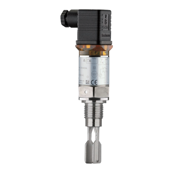
Indication of the switching status
The switching status of the electronics can be checked via the signal
lamps (LEDs) integrated in the upper part of the housing.
The signal lamps have the following meaning:
•
Green lights - voltage supply connected
•
Yellow lights - vibrating element covered
•
Red lights briefly - function test during instrument start (for 0.5 s)
•
Red lights - shortcircuit or overload in the load circuit (sensor
output high-impedance)
•
Red flashes - Error on the vibrating element or the electronics
(sensor output high impedance)
6.2
Simulation
The SITRANS LVL100 has an integrated function for simulation of the
output signal which can be activated magnetically. Please proceed as
follows:
→
Hold the test magnet (accessory) against the circle symbol with
the label "TEST" on the instrument housing
Fig. 12: Simulation of the output signal
The test magnet changes the current switching condition of the instru-
ment. You can check the change on the signal lamp. Please note that
all connected device are activated during the simulation.
If SITRANS LVL100 does not switch over after several tests with the
test magnet, you have to check the plug connection and the con-
nection cable and try it again. If there is no switching function, the
electronics will be defective. In this case you have to exchange the
electronics or return the instrument to our repair department.
SITRANS LVL100 - Operating Instructions