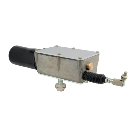
ACTUS 720-0108 Temel Kurulum - Sayfa 4
Kontrolör ACTUS 720-0108 için çevrimiçi göz atın veya pdf Temel Kurulum indirin. ACTUS 720-0108 7 sayfaları.

720 SERIES ACTUATOR – TROUBLESHOOTING GUIDE
In the event of failure or improper operation, please follow the steps outlined
below.
System Check
1.
Double check all wiring. Make sure you are using the Actus wiring
diagram drawing number 999-0172. Proper wiring technique is critical.
90% of all field problems can be traced to a poor connection or improper
wiring. Please check the following areas:
a. All wires and cables should be tied down and positioned so they can
not be accidentally pulled or knocked loose. All wiring subject to high
temperature or vibration should be run through a loom to protect it
from shorting to the vehicle frames.
b. Double check all ground wires as shown on the wiring diagram. All
frame grounds should be free of corrosion, paint, and dirt. Wires
shown running directly to the negative post of the battery should be
attached to a similar good direct ground. Frame grounding is not
recommended for these wires. Note that this actuator is grounded
with terminal #3. Terminals #4 and #5 provide bidirectional motor
control. Improper ground will make the limit switches fail to operate
properly.
c. This is a negative ground, 12 or 24 VDC system. Be sure correct
power is applied and regulated.
d. Check system fuse/circuit breaker for proper indication.
e. Certain motor speeds require different wiring. Check the truth table
on the wiring diagram.
2.
Check the actuator mounting position. The actuator should move the
device freely without binding. Temporarily disconnect linkage to remove
any load from actuator.
090407AJN
