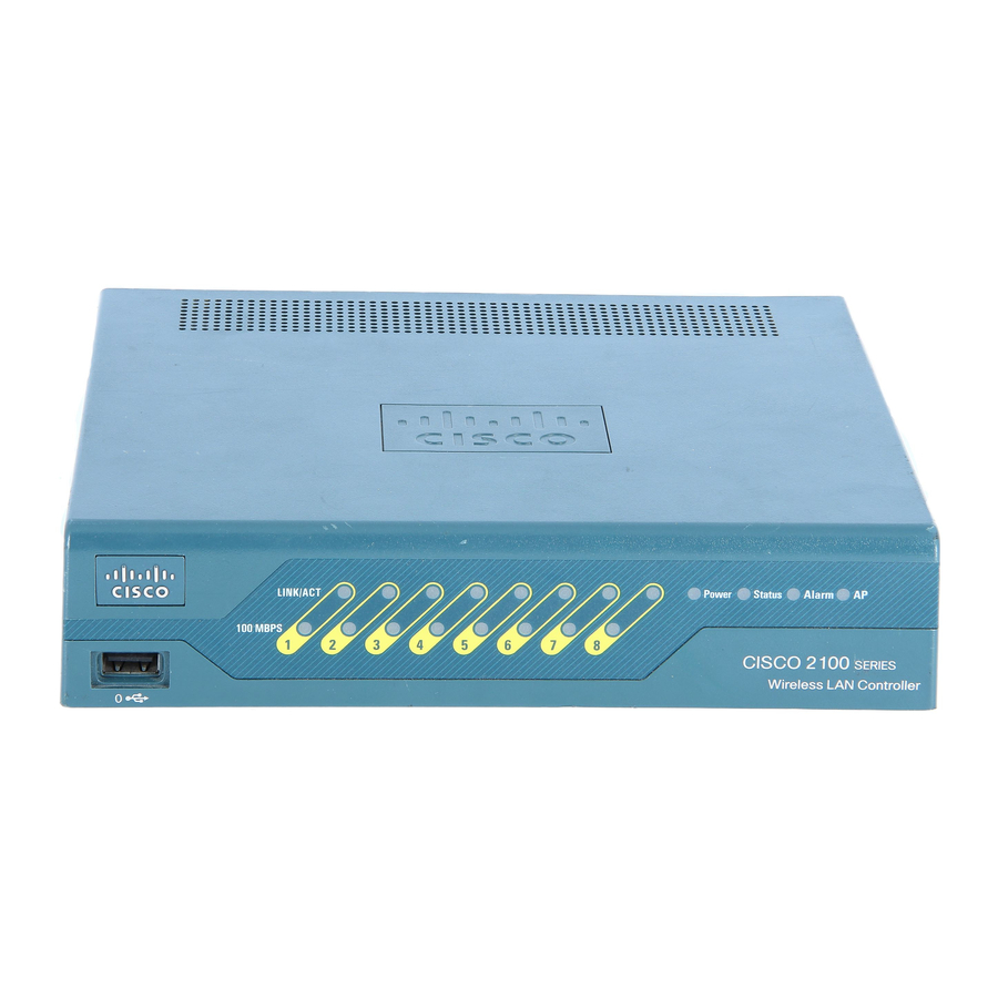
Cisco 5500 Series Kurulum Kılavuzu - Sayfa 6
Ağ Donanımı Cisco 5500 Series için çevrimiçi göz atın veya pdf Kurulum Kılavuzu indirin. Cisco 5500 Series 34 sayfaları. Cisco 8500 series
wireless lan controller
Ayrıca Cisco 5500 Series için: Yapılandırma Kılavuzu (40 sayfalar), Manuel (19 sayfalar), Yapılandırma Kılavuzu (50 sayfalar)

Controller Overview
Table 1
LED
RP/SP port
USB0/USB1 port
Console port (RJ-45)
Console port (mini-USB
Type B)
Distribution ports 1-8
Power supplies (PS1 and
PS2)
Cisco 5500 Series Wireless Controller Installation Guide
6
LED Indicators
Description
Off: Not present.
Green: Indicates RP/SP port is active and link is established.
Amber: Present with failure.
Off: Not present.
Green: Present and enabled.
Amber: Present with failure.
Green: Indicates active console port.
When this LED is on, the USB console port LED is off.
Green: Indicates active aux port.
When this LED is on, the RJ-45 console port LED is off.
Off: Not present.
Green: Indicates SFP port is active and link is established.
Amber: Present with failure.
Continuous green: Indicates that the power supply is operational.
Blinks green: Indicates that a power supply is installed but does not have
AC power.
Verify that the power cord in installed correctly and that the power
Note
switch is on.
Blinks amber: Indicates that the standby power supply fan is not spinning
or that the power supply is over temperature.
Continuous amber: Indicates that the power supply is in failure condition.
When the PS1 or PS2 LED is amber, the power supply shuts down.
Note
78-18998-01
