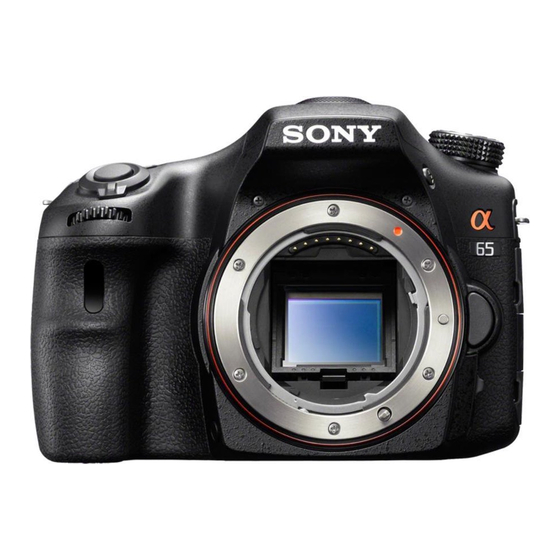
Sony Alpha SLT-A65 Servis Kılavuzu - Sayfa 18
Dijital Kamera Sony Alpha SLT-A65 için çevrimiçi göz atın veya pdf Servis Kılavuzu indirin. Sony Alpha SLT-A65 36 sayfaları. Correction and notes on shooting with the viewfinder
Ayrıca Sony Alpha SLT-A65 için: Düzeltme (2 sayfalar), İşlev Kılavuzu (3 sayfalar)

NOTE FOR REPAIR
• Make sure that the flat cable and flexible board are not cracked
of bent at the terminal.
Do not insert the cable insufficiently nor crookedly.
• When remove a connector, don't pull at wire of connector. It is
possible that a wire is snapped.
• When installing a connector, don't press down at wire of con-
nector.
It is possible that a wire is snapped.
• Do not apply excessive load to the gilded flexible board.
DISCHARGING OF THE CHARGING
CAPACITOR (C901)
The charging capacitor is charged up to the maximum 315 V
potential.
There is a danger of electric shock by this high voltage when the
capacitor is handled by hand. The electric shock is caused by the
charged voltage which is kept without discharging when the main
power of the unit is simply turned off. Therefore, the remaining
voltage must be discharged as described below.
Preparing the Short Jig
To preparing the short jig, a small clip is attached to each end of
a resistor of 1 kΩ /1 W (1-215-869-11).
Wrap insulating tape fully around the leads of the resistor to
prevent electrical shock.
1 kΩ/1 W
1 kΩ/1 W
Wrap insulating tape.
Wrap insulating tape.
SUBSIDIARY MATERIALS
G: Grease
G-15 (J-6082-619-A)
G-85 (J-6082-626-A)
G-116 (J-6082-628-A)
SLT-A65/A65K/A65L/A65M/A65V/A65VK/A65VL/A65VM/A65VX/A65VY/A65X/A65Y_L2
– ENGLISH –
Cut and remove the part of gilt
Cut and remove the part of gilt
which comes off at the point.
which comes off at the point.
(Be careful or some
(Be careful or some
pieces of gilt may be left inside)
pieces of gilt may be left inside)
Note: High-voltage cautions
Discharging the Capacitor
Short-circuit between two points with
the short jig about 10 seconds.
R: 1 kΩ / 1 W
(Part code: 1-215-869-11)
AM-026 Board
AM-026 Board
2-2
修理時の注意
• フラットケーブルおよびフレキシブル基板の端子面に欠け,
折れ等がないことを確認する。
また,コネクタへの接続は,差し込み不足や斜め差しになら
ないように注意する。
• コネクタを取り外す時に,線材部 (極細) を持って引っ張ると
断線する恐れがありますので,絶対に線材部 (極細) を持って
引っ張らないでください。
• 線材部 (極細) を押さえながらコネクタを差し込むと,線材部
(極細) が断線する恐れがありますので,絶対に線材部 (極細)
には負担をかけないでください。
• 金メッキされているフレキシブル基板には,強い負担をかけ
ないでください。
ストロボ用充電コンデンサ (C901) の放電
ストロボ用充電コンデンサは最大315Vの電圧で充電され
ています。
この高電圧で充電されたコンデンサに手を触れた場合,
電気ショックを受けます。この高電圧には単にセットの
電源を切っただけでは放電されず,残留しています。こ
のため,下記の方法で残留電圧を放電してください。
ショート治具の準備
ショート治具は1kΩ/1W抵抗 (1-215-869-11)
小型のクリップを接続して作成します。
抵抗器は絶縁テープで完全に覆い電気ショックを受けな
いようにしてください。
1 kΩ/1 W
1 kΩ/1 W
副資材
G : Grease
G-15 (J-6082-619-A)
G-85 (J-6082-626-A)
G-116 (J-6082-628-A)
– JAPANESE –
コンデンサの放電
フラッシュユニットの電源コンデンサ
の端子間をショート治具で約10秒間
接続する。
R: 1 kΩ / 1 W
(Part code: 1-215-869-11)
AM-026 Board
AM-026 Board
