Cisco Catalyst 5500 Manuel - Sayfa 2
Ağ Donanımı Cisco Catalyst 5500 için çevrimiçi göz atın veya pdf Manuel indirin. Cisco Catalyst 5500 19 sayfaları. Multiswitch router

Checking Equipment Status
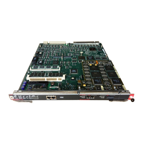
Supervisor Engine Module LEDs
The front panel of the supervisor engine III (product number WS X5530-E3) is shown in
Figure 7-1
WS-x5530
SUPERVISOR ENGINE I I I
The LEDs on the supervisor engine front panel indicate the status of the system, which includes the
supervisor engine, the power supplies, and the fan assembly.
Table 7-1
LED
SYSTEM
STATUS
FAN
PS1
PS2
SWITCH
LOAD
ACTIVE
Cisco MGC Software Release 7 Operations, Maintenance, and Troubleshooting Guide
7-2
Supervisor Engine III Front Panel
Console and Auxiliary ports
100%
CONSOLE
AUX
Switch
Load
Status
Reset
Switch
LEDs
button
Load display
Supervisor Engine III and Uplink Module LED Descriptions
State
Description
Green
Indicates that a series of self-tests and diagnostic tests has been passed.
Red
System is being booted or is faulty (fails a test or module is disabled).
Orange
Fan modules have failed or redundant power supply is installed, but not
turned on.
Green
The fan is operational.
Red
The fan is not operational.
Green
Power supply in left bay is operational.
Red
Power supply in left bay is not operational, switched off, or not receiving
power.
Off
Power supply in the left bay is off or not installed.
Note
Green
The power supply in the right bay is operational.
Red
The power supply in the right bay is not operational, is switched off, or
is not receiving input power.
Off
The power supply in the right bay is off or is not installed.
Note
1–100%
If the switch is operational, the switch load display indicates (as an
approximate percentage) the current traffic load over the backplane.
Green
The supervisor engine is operational and active.
Orange
The supervisor engine module is in standby mode.
Chapter 7
Maintaining the Cisco Catalyst 5500 Multiswitch Router
WS-U5531-FETX
MDIX
10/100Mbps
LINK
PCMCIA
10/100 FAST ETHERCHANNEL
PCMCIA slots
Uplink ports
The Catalyst 5500 power supply LED is red when no modules
are installed.
The Catalyst 5500 power supply LED is red when no modules
are installed.
PORT 2
MDIX
10/100Mbps
LINK
Table 7-1
describes LED operation.
Figure
7-1.
OL-0542-06
