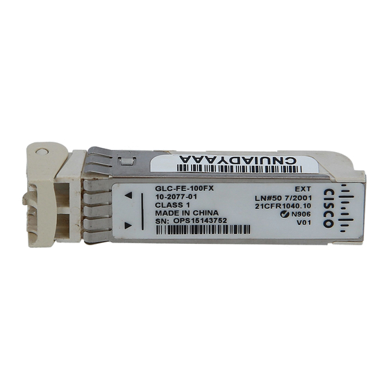
Cisco GLC-FE-100LX Bakım ve Sorun Giderme Kılavuzu - Sayfa 10
Ağ Donanımı Cisco GLC-FE-100LX için çevrimiçi göz atın veya pdf Bakım ve Sorun Giderme Kılavuzu indirin. Cisco GLC-FE-100LX 17 sayfaları. Small form-factor pluggable (sfp) transceiver modules
Ayrıca Cisco GLC-FE-100LX için: Veri Sayfası (9 sayfalar)

3. Check the label on the SFP transceiver body to verify that you have the correct model for your
network.
4. Find the send (TX) and receive (RX) markings that identify the top side of the SFP transceiver.
Note: On some SFP transceivers, the TX and RX marking might be replaced by arrowheads that
point from the SFP transceiver connector (transmit direction or TX) and toward the connector
(receive direction or RX).
5. Position the SFP transceiver in front of the socket opening.
Note: Different Cisco devices have different SFP module socket configurations. Your Cisco device
could have either a latch-up or a latch-down orientation. Ensure that you are installing the SFP
transceiver in the correct orientation for your Cisco device. Refer to the hardware installation
instructions that came with your Cisco device for more details.
6. Insert the SFP transceiver into the socket until you feel the SFP Transceiver Module connector
snap into place in the socket connector.
Note: For optical SFP transceivers, before you remove the dust plugs and make any optical
connections, observe these guidelines:
Always keep the protective dust plugs on the unplugged fiber-optic cable connectors and the
transceiver optical bores until you are ready to make a connection.
Always inspect and clean the LC connector end-faces just before you make any
connections. See the
Always grasp the LC connector housing to plug or unplug a fiber-optic cable.
7. Remove the dust plugs from the network interface cable LC connectors. Save the dust plugs for
future use.
8. Remove the dust plugs from the SFP transceiver optical bores.
9. Immediately attach the network interface cable LC connector to the SFP transceiver.
10. Connect the 1000BASE-T SFP transceivers to a copper network.
Caution: In order to comply with GR-1089 intrabuilding lightning immunity requirements,
you must use grounded, shielded, twisted-pair Category 5 cabling.
Complete these steps in order to connect the transceivers to a copper network:
a. Insert the Category 5 network cable RJ-45 connector into the SFP transceiver RJ-45
connector.
When you connect to a 1000BASE-T-compatible server, workstation, or router, use four
twisted-pair, straight-through Category 5 cabling for the SFP transceiver port. When you
connect to a 1000BASE-T-compatible switch or repeater, use four twisted-pair, crossover
Category 5 cabling.
b. Insert the other end of the network cable into an RJ-45 connector on a 1000BASE-T-
compatible target device.
11. Observe the port status LED:
Required Tools
section of this document for more information.
