Digitrax DS78V Talimatlar Kılavuzu - Sayfa 2
Kontrol Sistemleri Digitrax DS78V için çevrimiçi göz atın veya pdf Talimatlar Kılavuzu indirin. Digitrax DS78V 8 sayfaları. Eight servo loconet stationary/accessory decoder for turnout control.

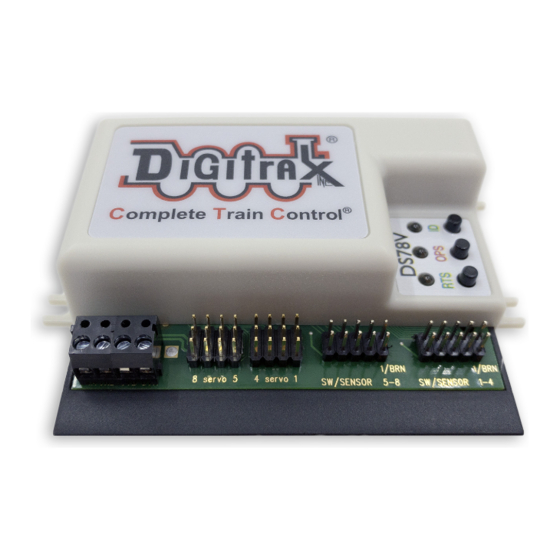
Figure 1: DS78V
System and Servo
output connections
To DCC Track
(Optional)
Servo#8, at Base Board
SW address +7
1.1 DS78V Quick Start - Eight 3-position semaphores:
To control eight servos driving 3-position semaphores using 16 switch addresses:
1.
Follow the steps of section 1.0 to power on DS78V and setup the Base SW#.
2.
Press and hold the OPS button for about 3 seconds until the green ID and
RTS LEDs blink alternately. Release the OPS button. The DS78V is now set-
up to configure Option Switch (OPSW) 1 to 40 by sending the required SW#
as Closed or Thrown to setup an option as T or C, as defined in Table 1.
3.
Issue a SW#3 Closed command. This sets OPSW3 to Closed (C). From
factory default 2-position mode this will configure the eight servo outputs to
the 3-position Semaphore mode, each controlled by 2 SW#'s.
4.
In Semaphore mode the DS78V will now respond to 16 SW consecutive ad-
dresses starting at the unit's Base SW#, in eight SW# pairs.
5.
A switch command to the Base SW# will set Servo1 at: full Clockwise angle
for T (semaphore STOP/RED) and full Counter-Clockwise for C (semaphore
CLEAR/GREEN), as viewed from the arm-end of the servo
6.
A switch command at Base SW#+1 will drive Servo1 to the mid-angle or Ap-
proach position (semaphore APPROACH/YELLOW) for either T or C.
7.
In this way, each servo responds to a consecutive pair of switch commands:
the first SW# as T/C and the SW#+1 for the Approach setting. For example:
Base SW#+3 sets T/C for Servo2 and Base SW#+4 for T or C sets the center
Approach angle setting for Servo2.
8.
Press and hold OPS button for about 3 seconds to now exit OPSW setup.
9.
Connect linkages from the servo arms to the semaphores as needed.
© 2021 Digitrax, Inc.
12V DC in
C
T
C
omplete
rain
ontrol
8
servo
5
4
servo
1
Servo examples in Thrown or
Clockwise arm orientation
as viewed from arm screw side
— 2 —
LocoNet
1/BRN
1/BRN
SW/SENSOR 5-8
SW/SENSOR 1-4
10 pin header cables
for 16 input line options
Servo#1, at Base Board SW address +0
(lowest Base Board SW address is 1)
www.digitrax.com
