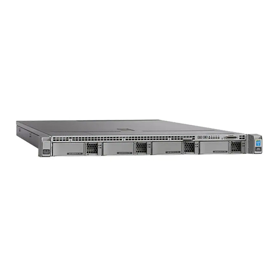
Cisco Sourcefire Defense Center 750 Hızlı Başlangıç Kılavuzu - Sayfa 2
Sunucu Cisco Sourcefire Defense Center 750 için çevrimiçi göz atın veya pdf Hızlı Başlangıç Kılavuzu indirin. Cisco Sourcefire Defense Center 750 4 sayfaları. Network management device
Ayrıca Cisco Sourcefire Defense Center 750 için: Başlangıç Kılavuzu (31 sayfalar)

DC750
Installing the Defense Center
The Sourcefire 3D System is delivered on different hardware platforms that you can
rack-mount. When you install a Defense Center, make sure that you can access the
Defense Center's console for initial setup.
You can access the console for the first configuration of a new Defense Center using a
keyboard and monitor with KVM, or using an Ethernet connection to the management
interface.
Keyboard and Monitor/KVM
You can connect a USB keyboard and VGA monitor to any Sourcefire Defense Center,
which is useful for rack-mounted Defense Centers connected to a keyboard, video, and
mouse (KVM) switch.
IMPORTANT! Do not use a KVM switch with USB mass storage to access the Defense
Center because the Defense Center may attempt to use the mass storage device as a
boot device.
Ethernet Connection to Management Interface
Configure a local computer, which must not be connected to the internet, with the
following network settings:
•
IP address:
•
netmask:
•
default gateway:
Using an Ethernet cable, connect the network interface on the local computer to the
management interface on the Defense Center. To interact with the Defense Center, use
terminal emulation software such as HyperTerminal or XModem. The settings for this
software are as follows:
•
9600 baud
•
8 data bits
•
no parity checking
•
1 stop bit
•
no flow control
Note that the management interface on a physical Sourcefire Defense Center
is preconfigured with a default IPv4 address. However, you can reconfigure the
management interface with an IPv6 address as part of the setup process.
Quick Start Guide - DC750
192.168.45.2
255.255.255.0
192.168.45.1
Page 2 of 4
INSTALLATION
2014-5.3-2
