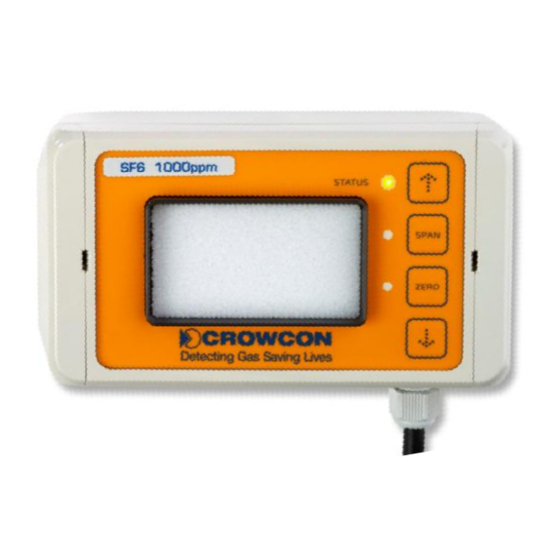
Crowcon 40/40R Kullanım ve Bakım Talimatları Kılavuzu - Sayfa 10
Gaz Dedektörleri Crowcon 40/40R için çevrimiçi göz atın veya pdf Kullanım ve Bakım Talimatları Kılavuzu indirin. Crowcon 40/40R 20 sayfaları. Infra-red sf6 and refrigerant gas detector

F-Gas Detector Instructions
JP6 connected (15V DC supply voltage required)
0..10V
When using the above mentioned configuration, the following voltage values can be
connected at the output:
0-20mA (JP3 not connected)
0V – 2V
2V (JP4)
0V – 5V
5V (JP5)
0V – 10V
10V (JP6)
Other link functions:
JP1: reserved for future use (RS-485 termination)
JP2: factory use only.
3.4.
Wire breaks
Should the communication between the IR sensor and the interface electronics be disrupted
during the operation of the transmitter, (unintentional disconnection or wire break), this
status will be displayed at the power output as follows:
Operation with 4-20mA
Operation with 0-20mA
Depending on the operating mode and the subsequent evaluation, aforesaid status can be
used for error detection.
If the fault is repaired, the transmitter will restart automatically with the regular startup phase,
then resume regular operation.
Note:
If the operating mode 0-20mA was selected, the frozen current value will be maintained until
the completion of the new start-up phase.
In general, the reliable detection of a wire break is only possible in operating modes 4-
20mA!
Output current will be frozen at 2mA.
the current value last issued will be frozen.
4-20mA (JP3 connected)
0.4 V – 2V
1.0V – 5V
2.0V – 10V
