Crowcon Flamgard-4/20 Kurulum, Kullanım ve Bakım Kılavuzu - Sayfa 2
Gaz Dedektörleri Crowcon Flamgard-4/20 için çevrimiçi göz atın veya pdf Kurulum, Kullanım ve Bakım Kılavuzu indirin. Crowcon Flamgard-4/20 3 sayfaları. Flameproof flammable gas detector
Gas Detection You Can Trust
Part No C01457
Flamgard-4/20
(formerly EXD90/FL)
Flameproof
Flammable Gas
Detector
4/20
Installation, operating and
maintenance instructions, M07177
1. INTRODUCTION
1.1 Product overview
Flamgard 4/20 is a flameproof flammable gas detector suitable
for use in Zone 1 or 2 hazardous areas. It is designed to detect
flammable gas, present in ambient air, at concentrations not
exceeding the Lower Explosive Limit (LEL) of the target gas for
which it is calibrated. Flamgard 4/20 is powered by 24 V dc
(nominally) and provides a 4-20 mA signal (sink or source)
proportional to the gas concentration. For a list of flammable
gases which Flamgard 4/20 can detect, please contact Crowcon.
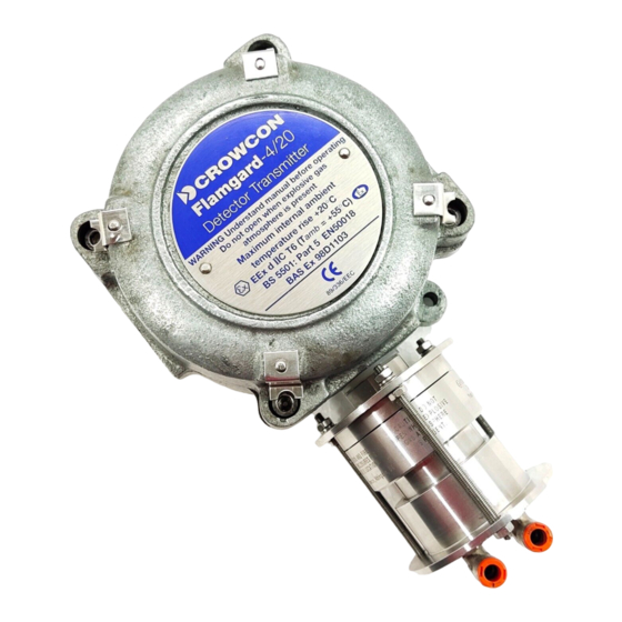
1.2 Product description
Flamgard 4/20 comprises three parts; a sensor housing, amplifier and
junction box.
Please note: 96HD sensor and amplifier unit (junction
box) have been certified seperately. 96HD: Sira02ATEX1283X and
Amplifier unit (junction box): Baseefa03ATEX0074.
The 96HD sensor housing is a modular stainless steel
assembly which dismantles to allow plug in pellistor sensors to be
replaced easily. The assembly is certified EEx d IIC T6 and screws into
the junction box.
The amplifier is mounted in the junction box. All electrical
connections to the detector are made via the terminal block on the
amplifier. The amplifier provides power to the pellistor sensor and
converts the gas reading into a 4-20 mA signal for connection to a control
panel.
The junction box is manufactured from galvanised cast iron and
is certified EEx d IIC T6. The junction box is supplied with 1 x M20 cable
entry for customer use. Alternative cable entries are available upon
request. Adaptors for NPTF entries are also available (see Section 4,
Spare Parts and Accessories).
Diagram 1 shows the Flamgard assembly with junction box
cover removed to show the amplifier and wiring details.
1
2. INSTALLATION
WARNING
Flamgard 4/20 is designed for use in Zone 1 and 2 hazardous
areas and is certified EEx d IIC T6. Installation must be in
accordance with the recognised standards of the appropriate
authority in the country concerned. For further information
please contact Crowcon. Prior to carrying out any installation
work ensure local regulations and site procedures are followed.
2.1 Location
There are no rules which dictate the siting and location of detectors,
however, considerable guidance is available from BS6959:1988 -
'British Standard Code of Practice for the Selection, Installation, Use and
Maintenance of Apparatus for the Detection and Measurement of
Combustible Gases', Similar international codes of practice may be used
where applicable. In addition certain regulatory bodies publish
specifications giving minimum gas detection requirements for specific
applications.
The detector should be mounted where the gas is most likely to
be present. The following points should be noted when locating
flammable gas detectors:
•
To detect gases which are lighter than air e.g. methane, detectors
should be mounted at high level and Crowcon recommend the use
of a Collector Cone, Part No. C01051.
•
To detect heavier than air gases e.g. butane, detectors should be
mounted at low level.
•
When locating detectors consider the possible damage caused by
natural events e.g. rain or flooding. For detectors mounted outdoors
Crowcon recommend the use of a Weatherproof Cap, Part No.
C01442.
•
Consider ease of access for functional testing and servicing.
•
Consider how the escaping gas may behave due to natural or forced
4
1. INTRODUCTION
Diagram 1: Flamgard 4/20 assembly
2
2. INSTALLATION
air currents. Mount detectors in ventilation ducts if appropriate.
•
Consider the process conditions. Butane is normally heavier than air,
but if released from a process line which is at an elevated
temperature and/or under pressure the gas may rise rather than fall.
The placement of sensors should be determined following
advice of experts having specialist knowledge of gas dispersion, the
plant processing equipment as well as safety and engineering issues.
The agreement reached on the locations of sensors should be
recorded. Crowcon would be pleased to assist in the selection and siting
of gas detectors.
2.2 Mounting
The mounting detail of Flamgard 4/20 is given in Diagram 1. Install
Flamgard at the designated location with the detector pointing down.
This ensures that dust or water will not collect on the sinter and stop gas
entering the detector. A Swivel Mounting Bracket (Part No. C01340) is
available to assist in the mounting of the detector if required.
2.3 Cabling requirement
Cabling to Flamgard 4/20 must be in accordance with the recognised
standards of the appropriate authority in the country concerned and meet
the electrical requirements of the detector. Crowcon recommend the use
of steel wire armoured (SWA) cable and suitable explosion proof glands
must be used. Alternative cabling techniques, such as steel conduit, may
be acceptable provided appropriate standards are met.
Flamgard 4/20 requires a dc supply of 10-30 V at up to 350 mA.
Ensure the minimum dc supply of 10 V is observed at the detector, taking
into account the voltage drop due to cable resistance.
For example, a nominal dc supply at the control panel of 24 V
has a guaranteed minimum supply of 18V. The maximum voltage drop
5
Diagram 2: 96HD assembly
3
allowed is therefore 8V. Flamgard 4/20 can demand up to 350 mA and so
the maximum loop resistance allowed is 22 Ohms. A 1.5 mm
cable will
2
typically allow cable runs up to 900 m. Table 1 shows maximum cable
distances given typical cable parameters.
C.S.A. (mm
2
)
Resistance (Ohms per km)
Max. Distance (km)
Cable
Loop
1.0
18.1
36.2
600
1.5
12.1
24.2
900
2.5
7.4
14.8
1400
Table 1: Maximum cable distances for typical cables
Acceptable cross sectional area of cable is 0.5 to 2.5 mm2. Table 1
provides guidance only, actual cable parameters for each application
should be used to calculate maximum cable distances.
2.4 Electrical connections
All connections are made via the 6 way terminal block mounted on the
amplifier in the junction box. The 3 wires from the 96HD are colour coded
and should be terminated in the corresponding colour coded terminal.
The remaining terminals marked '+','-' and 'Signal' are connected to the
control equipment. Flamgard 4/20 is factory set as a 4-20 mA source
device unless specified otherwise when ordering. This is set via an
internal switch in the amplifier and may be changed to 'sink' on site if
necessary. Diagram 3 summarises the electrical connections.
Note: The junction box and cable armour must be earthed at the
detector or control panel to limit the effect of radio frequency
interference, and to maintain electrical safety.
6