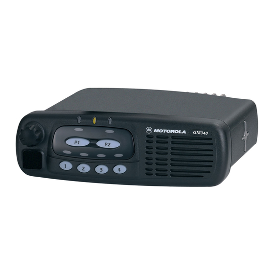
Motorola GM160 Temel Servis Kılavuzu - Sayfa 25
İki Yönlü Telsiz Motorola GM160 için çevrimiçi göz atın veya pdf Temel Servis Kılavuzu indirin. Motorola GM160 46 sayfaları. Professional radio
Ayrıca Motorola GM160 için: Hizmet Bilgileri (34 sayfalar), Kullanıcı Kılavuzu (44 sayfalar), Hizmet Bilgileri (32 sayfalar), Hizmet Bilgileri (32 sayfalar), Kullanıcı Kılavuzu (44 sayfalar)

Radio Assembly
5.
Remove the display and the top and bottom elastomeric connectors from the control head
housing (GM360 only).
NOTE Care should be taken not to touch or contaminate the conductive pads on the under side of
the keypad, the elastomeric connectors or the conductive contacts on the printed circuit
board .
7.0
Radio Assembly
7.1
Control Head - GM340
1.
Locate the speaker in the control head and press it into place as shown in Figure 3-8.
2.
Insert the keypad into the control head ensuring that the keypad keys and connector cut-out fit
correctly.
NOTE Care should be taken not to touch or contaminate the conductive pads on the underside of
the keypad.
3.
On the board, rotate the on/off control spindle fully counter-clockwise.
4.
Also, rotate the volume knob on the housing fully counter-clockwise
5.
Align the board with the control head and insert the on/off control spindle through the hole in
the keypad.
6.
Locate the two snap tags on the board in the grooves in the control head and press the board
into place until all of the tags snap into place.
7.
Connect the speaker connector to the connector on the board.
7.2
Control Heads - GM360 and GM380
1.
On the GM360 only, locate the display in the control head ensuring that the two cut-outs in the
display are aligned with their corresponding indentations, then press the display into place.
Insert the top and bottom elastomeric connector strips into the spaces above and below the
display respectively.
NOTE Care should be taken not to touch or contaminate the conductive pads on the underside of
the display and the elastomeric connectors (GM360 only).
2.
Fit the rubber keypad onto the board ensuring that the on/off control and microphone
connector on the board locate correctly with the cut-outs in the keypad.
3.
On the board, rotate the on/off control spindle fully counter-clockwise.
4.
Also, rotate the volume knob on the front housing fully counter-clockwise.
5.
Align the board with the control head, inserting the on/off control spindle and microphone
connector through the holes in the control head.
6.
Ensure that the keypad, on/off control spindle and microphone connector are aligned with the
control head then press the board into place until it clicks.
7.
On the GM360, insert the speaker tube and speaker into the control head and press it in until
it clicks.Connect the speaker connector to the board.
3-9
