Motorola CDM1250 Servis ve Kurulum Kılavuzu - Sayfa 10
Radyo Motorola CDM1250 için çevrimiçi göz atın veya pdf Servis ve Kurulum Kılavuzu indirin. Motorola CDM1250 32 sayfaları. Cdm-series control station
Ayrıca Motorola CDM1250 için: Kullanıcı Kılavuzu (50 sayfalar)

Introduction to the CDM Control Station
Cables
CDM Control Station Interface Circuit
Boards
The Control Station contains three circuit boards and an
internal speaker that together provide the enhanced control
functions. The Control Station Interface Module (CSIM) is
the main board located beneath the radio inside the inner
chassis and mounted using card guides. This module con-
tains all logic, control, and interface circuitry. The Control
Station Audio Panel (CSAP) is located on the housing base
just behind the front panel. It provides the physical external
audio accessory connectors. The Control Station Key Panel
(CSKP) assembly is located on the front panel and provides
the buttons and LED indicators necessary for local dispatch
operation. A speaker is mounted to the front panel of the cab-
inet which allows for monitoring of radio receive audio,
accessory intercom, and accessory transmit audio.
Cables
The coaxial cables that connect the radio to the Control Sta-
tion back panel are fabricated from RG58A/U (the cable
used with most of the mobile antenna kits). Do not use
RG58A/U as the coaxial cable that connects the antenna con-
nector of the Control Station to the antenna. The rather small
size of the RG58A/U can introduce excessive losses in the
system that will decrease the effective range of the Control
Station.
1-2
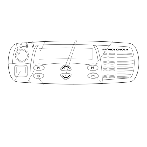
Figure 1-1. CDM Control Station
Substitute RG400/U for short lengths and RG214/U or 1/2-
inch "hardline" for the longer lengths. If the "hardline" is
used, connect the antenna connector of the Control Station to
the end of the "hardline" with a flexible jumper cable. This
will avoid undue stress on the connectors of the cables and
the Control Station.
Table 1-1 can be used to determine which feedline to choose
for a given frequency band and line length to maintain 1.5 dB
(approximately 30%) or less power loss. Table 1-2 is a list of
Motorola part numbers for the various connectors and
cables.
Table 1-1. Maximum Feedline Length in Feet (Meters)
Low (50 MHz)
VHF (150 MHz)
UHF (450 MHz)
800 MHz
mini-UHF male connector
UHF male connector
6880309N15-A
Band
RG400/U
55 (17)
25 (7.5)
15 (4.5)
10 (3)
Table 1-2. Part Numbers for
Connectors/Cables
Part
Motorola Part Number
CDM Control Station
RG214/U
Hardline
100 (30)
300 (90)
50 (15)
150 (45)
25 (7.5)
90 (27)
20 (6)
70 (21)
2884606M01
2884579F04
October, 2004
