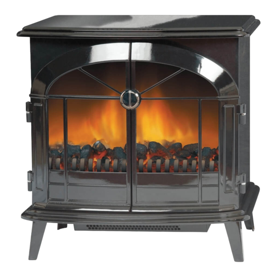
Dimplex 143348BK Kurulum ve Kullanım Talimatları - Sayfa 3
Soba Dimplex 143348BK için çevrimiçi göz atın veya pdf Kurulum ve Kullanım Talimatları indirin. Dimplex 143348BK 5 sayfaları.

Operation
The controls are located behind the
Connect the fire to your electricity supply.
T
Controls
Note: When either the remote control or the manual controls
are used, the neon's will come on for 3 seconds indicating
the relevant setting (see fig. 3).
Battery information
1.
Slide open the battery cover on the back of the remote
control
2.
Install two AAA batteries into the remote control (see
Fig. 4)
3.
Replace the battery cover.
Discard leaky batteries
Dispose of batteries in the proper manner according to
Provincial and local regulations. Any battery may leak electrolyte
if mixed with a different battery type, if inserted incorrectly, if all
the batteries are not replaced at the same time, if disposed of
in a fire or if an attempt is made to charge a battery not intended
to be recharged.
doors (see Fig. 2).
Fig. 2
neon's for indicating
the operation level
Fig. 3
Batteries
Fig. 4
Remote Control
Warning: it takes time for
the receiver to respond
to the transmitter. Do not
press the buttons more
than once within two
seconds for correct
operation.
Manual or Remote Operation
Setting
Operation
Flame effect
Press the 'I' button once
Flame effect & 1kW heat
Press the 'I' button again
Flame effect & 2kW heat
Press the 'I' button again
To turn off any of the
Press the
settings
Note : The ON/OFF Switch must first be turned on to
operate either the manual or the remote controls.
Thermostat (T) - see Fig. 2
In order to maintain a certain room temperature, set
thecontroller to 'max.'. Operate the appliance at full power
untilthe required room temperature is reached. Set back
thethermostatic controller until the appliance switches off
withan audible "click". This temperature will be kept
almostconstant by the thermostatic control switching on
and offautomatically.Please note that the appliance can
only beswitched on when the thermostat setting is higher
then theroom temperature.
Thermal Safety Cut-out
A thermal safety cut-out is incorporated in the heater to
prevent damage due to overheating.
This can happen if the heat outlet was restricted in any way.
The heater will switch on once the obstruction has been
removed and the heater has cooled. If the cut-out continues
to operate intermittently, the heater should be switched off
and a service agent contacted.
Maintenance
WARNING: ALWAYS DISCONNECT FROM THE POWER
SUPPLY BEFORE ATTEMPTING ANY MAINTENANCE.
= Standby
= On
Fig. 5
OFF
ON
Indication
Bottom Neon
Bottom &
Middle Neon
All 3 Neon's
button once
