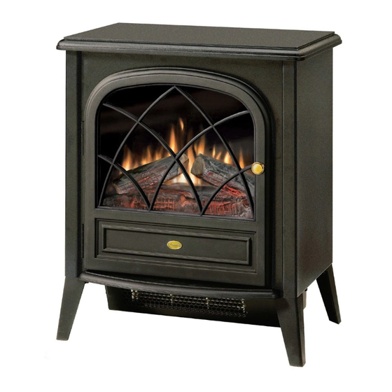
Dimplex ELECTRALOG CS2307 Servis Kılavuzu - Sayfa 7
Soba Dimplex ELECTRALOG CS2307 için çevrimiçi göz atın veya pdf Servis Kılavuzu indirin. Dimplex ELECTRALOG CS2307 11 sayfaları. Compact stove
Ayrıca Dimplex ELECTRALOG CS2307 için: Kullanıcı El Kitabı (14 sayfalar), Servis Kılavuzu (13 sayfalar), Servis Kılavuzu (13 sayfalar)

- 1. Table of Contents
- 2. Operation
- 3. Replacement Parts List
- 4. Exploded Parts Diagram
- 5. Wiring Diagram
- 6. Light Bulb Replacement
- 7. Mirror Replacement
- 8. Switch Replacement
- 9. Flicker Motor/Flicker Rod Replacement
- 10. Remote Control Replacement
- 11. Heater Assembly/Cutout Replacement
- 12. Thermostat Replacement
- 13. Power Cord Replacement
screws along each side; and three (3) screws at the front,
accessible behind the door.
3. Remove top panel.
4. Locate switch to be replaced and disconnect the wiring
clips, noting their original locations.
3 Position ON/OFF Switch
The 3 Position ON/OFF Switch is located in the far upper left
corner at the back of the stove (Figure 5). The Switch has
three (3) wire clips to remove.
Heater ON/OFF Switch
The Heater ON/OFF Switch is located in the far upper left
corner at the back of the stove, under the 3 Position ON/
OFF Switch (Figure 5). The Switch has two (2) wire clips to
remove.
Figure 5
Retainer Clip
3 Position
ON/OFF
Heater
Switch
ON/OFF
Switch
5. Depress the two (2) retainer clips on the switch to be
replaced (one (1) per side) and push the switch out from
the back panel of the stove.
6. Properly orientate replacement switch and push into back
panel until retainer clips snap into place.
7. Reconnect switch with wire clips removed in step 4.
8. Reattach top panel to stove using screws removed in
step 2.
Flicker Motor/Flicker Rod Replacement
If the stove was operating prior to servicing allow at least
10 minutes for light bulbs and heating element to cool off to
avoid accidental burning of skin.
Disconnect power before attempting any maintenance or
cleaning to reduce the risk of electric shock or damage to
persons.
Replacement Procedure:
1. Open stove door.
Wire Clips
Thermostat
Thermostat
Knob
2. Remove the 11 Philips screws that attach the top panel to
the stove as shown in Figure 4 (page 6). There are: four
(4) screws along each side; and three (3) screws at the
front, accessible behind the door.
3. Remove top panel.
4. Slide mirror up from within the stove to remove.
5. Remove the log set by removing the two (2) inside Philips
screws as shown in Figure 6.
Figure 6
Mirror
Log Set Screws (2)
6. Pull Flicker Rod as far right (towards Flicker Motor) as
possible and remove by cautiously bending the rod just
enough for it to clear the mounting bracket on the left.
7. Close the stove door and turn the stove onto its back.
8. Remove four (4) Philips screws as shown in Figure 7 to
release the bottom pan.
Figure 7
7
Top Panel
Flicker Rod
Screws to remove
Flicker
Motor
