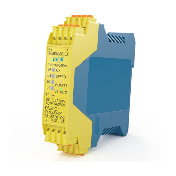
DINA DN3PD1 Geçici Kullanım Kılavuzu - Sayfa 5
Endüstriyel Ekipmanlar DINA DN3PD1 için çevrimiçi göz atın veya pdf Geçici Kullanım Kılavuzu indirin. DINA DN3PD1 8 sayfaları. Speed monitoring for one and three phases motors without sensor system
Ayrıca DINA DN3PD1 için: Orijinal Kullanım Kılavuzu (20 sayfalar)

DN3PD1
Vorläufige Betriebsanleitung
Geräteanschluss
Messeingänge < 690V AC
A1
Betriebsspannung
Power supply
• Die Klemmen L1, L2 und L3 an DN3PD1 müssen ständig
mit den Klemmen der Betriebsspannung des zu überwach-
enden Motors verbunden sein. Im anderen Falle schaltet
die Drahtbruchkontrolle die Ausgangskontakte ab.
• Bei einphasiger Beschaltung müssen die Klemmen L1 und
L3 an DN3PD1 verbunden sein.
• Die Eingangsspannung an den Klemmen darf 690V AC
nicht überschreiten.
• Die Leitungen zwischen Motor und DN3PD1 sind nur als
Messleitungen zu verwenden.
• Für den Anschluss von DN3PD1 an einen Motor sollen
Hochstromklemmen mit Prüfabgriff eingesetzt werden.
Funktion der Ausgänge
Eingangsfrequenz
außerhalb
des
parametrierten
Bereiches
O1: 24V
O2: 24V
13
14 23
Stand: 18.12.2016
DN3PD1
< 3x690V
L1 L2
L1
L2
L1, L2 und L2:
b8
OK
b4
Speed
b2
b1
24V
24V
A2
24VDC
0V
O1
O2
Diagnose Ausgänge Not-Halt oder Schutzeinrichtung verriegeln
Diagnostic outputs
Input
frequency
outside of the
configured
range
0V
24V
24
Seite 5 von 8
Temporary instruction manual
Schematic 1
M
3
L3
L1, L2 and L2:
Measuring inputs < 690V AC
Steuerelektronik
control electronic
13 14
Emergency stop or safety cover lock
• The terminals L1, L2 and L3 at DN3PD1 have to be
permanently connected to the terminals of the
power supply of the motor. Otherwise the wire
break monitoring opens the output contacts.
• For one phase mode the terminal L1 and L3 have to
be connected together.
• The terminal input voltage must not exceed
690V AC.
• The wiring between motor and DN3PD1 is
intended as measuring connection only.
• To connect DN3PD1 to the motor high current
terminals with integrated test points shall be used.
Eingangsfrequenz
innerhalb
des
parametrierten
Bereiches
O1: 24V
24V
24V
O2: 24V
13
14 23
Date: 2016-12-18
Equipment connection
L (U1)
N (U2)
L3
Anschluss
1 Phasenmotor
Connection
one phase motor
23 24
Function of the outputs
Input
frequency
inside of the
configured
range
O1: 24V
O2: 24V
13
24
Schematic 2
M
1
L1
L3
Fehlerfall
Error
0V
0V
14 23
24
Page 5 of 8
