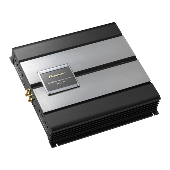
Pioneer PRS-A700 Servis Kılavuzu - Sayfa 25
Amplifikatör Pioneer PRS-A700 için çevrimiçi göz atın veya pdf Servis Kılavuzu indirin. Pioneer PRS-A700 28 sayfaları. Bridgeable 4-channel power amplifier

5
QQ
3 7 63 1515 0
6. ADJUSTMENT
- Connection Diagram
R566
R562
TE
L 13942296513
R511
R515
Idling Current Adjustment
No.
1
2
3
4
www
Note:
1. The idle current should be set when the amplifier has not been in operation for a long time and also should be
set when at room temperature.
.
2. PCB assembly must be mounted in the heatsink and all power transistors must be attached to the heatsink using
the proper fastners.
5
http://www.xiaoyu163.com
+
+
DC V Meter(2)
DC V Meter(4)
-
-
R516
R512
VR452
VR402
VR401
VR451
R561
R565
+
+
DC V Meter(1)
DC V Meter(3)
-
-
Adjustment Point
VR401(A Lch)
VR402(A Rch)
VR451(B Lch)
VR452(B Rch)
x
ao
y
i
http://www.xiaoyu163.com
6
8
Q Q
3
6 7
1 3
u163
.
PRS-A700/X1H/EW
6
7
2 9
9 4
2 8
1 5
0 5
8
2 9
9 4
Adjustment Method
+
DC V Meter(1) : 7.7 1.1mV
+
DC V Meter(2) : 7.7 1.1mV
+
DC V Meter(3) : 7.7 1.1mV
+
DC V Meter(4) : 7.7 1.1mV
m
co
7
8
9 9
A
SIDE A
B
C
2 8
9 9
D
E
F
25
8
