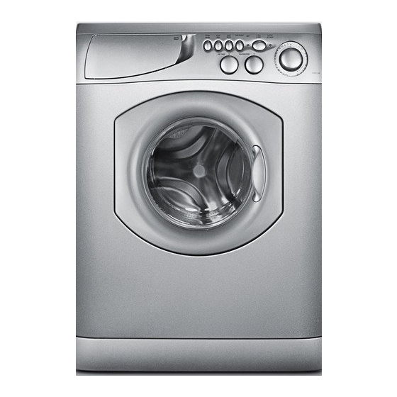
Ariston AW 125 Onarım Kılavuzu - Sayfa 6
Yıkayıcı Ariston AW 125 için çevrimiçi göz atın veya pdf Onarım Kılavuzu indirin. Ariston AW 125 20 sayfaları. Washer / washer-dryer combo
Ayrıca Ariston AW 125 için: Kullanıcı Kılavuzu (23 sayfalar)

- 1. Table of Contents
- 2. Model & Serial Number Locations
- 3. Top Panel
- 4. Control Panel
- 5. Control Panel Components
- 6. Toe Kick & Drain Motor
- 7. Drum Boot
- 8. Door Switch
- 9. Water Valves
- 10. Heater Assembly (AWD 120 / 121 / 129 Only)
- 11. Pressure Switch
- 12. Rear Access Panel
- 13. Control Board
- 14. Main Motor
- 15. Fault Codes
- 16. Schematics
3. CONTROL PANEL
• To remove the Control Panel, first remove the two Phillips screws located on the top corners of the Control Panel (Fig 3-1).
• Next, remove the Soap Dispenser by grasping it firmly and sliding it out from its housing (Fig. 3-2). Now, remove the Dispenser
Door and Program Guide by lifting out the Hinge Pin (Fig. 3-3) the pin will easily slide up and out. With the Soap Dispenser and
Door completely removed you can remove the two (2) remaining Phillips Screws.
TECH NOTE: When re-installing the Control Panel make sure the bottom edge of the Soap Dispenser Housing rests on top of the
Control Panel opening as shown in the box of Fig. 3-4.
• Next, remove the wiring from each Switch and the Program Selector. To remove the Switch wiring simply press the Locking Tab
forward and slide the Wiring Connector up and out (Fig. 3-5). Now release the two (2) remaining Control Panel Locking Tabs
located on the bottom rear of the Control Panel (Fig. 3-6) and the complete Control Panel Assembly can be removed.
REPAIR MANUAL
Fig. 3-2
Fig. 3-5
Fig. 3-3
AW 120 / AW 122 / AW 125
AWD 120 / AWD 121 / AWD 129
Fig. 3-1
Fig. 3-4
Fig. 3-6
Page: 3
