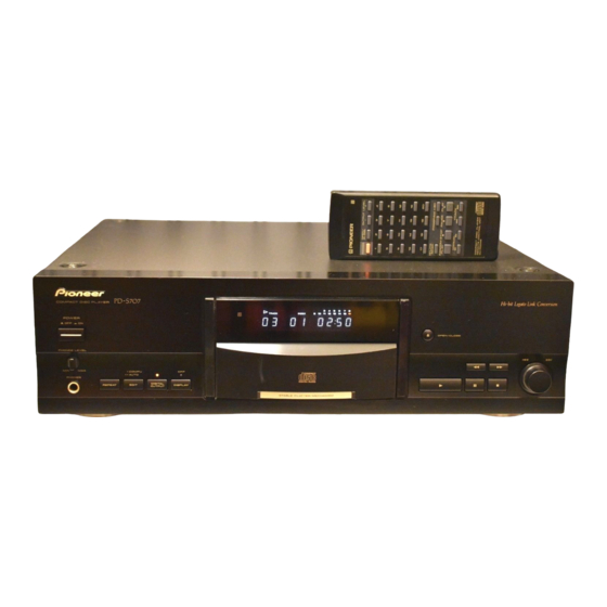
Pioneer PD-S707 Servis Kılavuzu - Sayfa 19
CD Çalar Pioneer PD-S707 için çevrimiçi göz atın veya pdf Servis Kılavuzu indirin. Pioneer PD-S707 41 sayfaları.

1
4. PCB CONNECTION DIAGRAM
NOTE FOR PCB DIAGRAMS:
1. Part numbers in PCB diagrams match those in the schematic
diagrams.
2. A comparison between the main parts of PCB and schematic
diagrams is shown below.
Symbol in PCB
Symbol in Schematic
Diagrams
Diagrams
B
C
E
B
C
E
B C E
B
C
E B
C
E
B C E
4.1 PHONE BOARD and MECHANISM BOARD ASSEMBLIES
PICKUP ASSY
E
PHONE BOARD ASSY
Q502
1
2
Symbol in PCB
Symbol in Schematic
Diagrams
Diagrams
D
G
Part Name
D G S
Transistor
Transistor
with resistor
G
MECHANISM BOARD ASSY
SPINDLE
MOTOR
SIDE A
Q501
IC501
2
3
Part Name
3. The parts mounted on this PCB include all necessary parts
S D
G
S
for several destination.
For further information for respective destinations, be sure
Field effect
transistor
to check with the schematic diagram.
4. Viewpoint of PCB diagrams
Connector
Resistor array
3-terminal
regulator
P. C. Board
PWX1192–
S610
CMK–54XT
INSIDE
M
1
4
CN610
SERVO MECHANISM ASSY T96
LOADING MECHANISM ASSY 96TT
E
PHONE BOARD ASSY
B
CN30
B
CN402
3
4
PD-S707
Capacitor
SIDE A
Chip Part
SIDE B
SIDE A
A
CN131
CARRIAGE
MOTOR
M
A
CN202
A
CN204
SIDE B
(PNP1449–B)
E G
4
A
B
C
D
19
