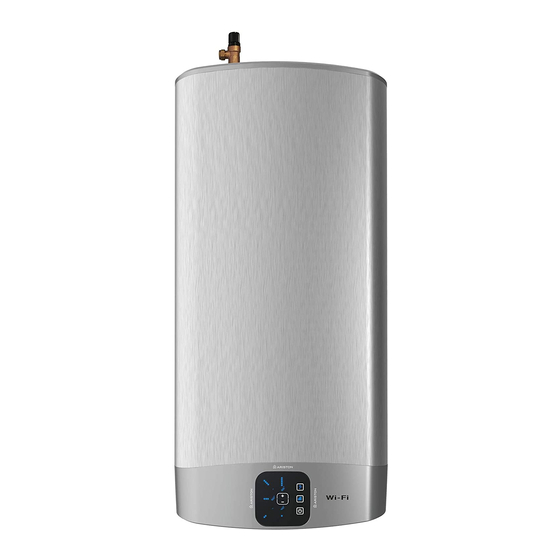
Ariston VLS EVO 80 Montaj ve Kullanım Talimatları Kılavuzu - Sayfa 14
Su Isıtıcı Ariston VLS EVO 80 için çevrimiçi göz atın veya pdf Montaj ve Kullanım Talimatları Kılavuzu indirin. Ariston VLS EVO 80 25 sayfaları. Unvented water heater

MAINTENANCE REGULATIONS (for qualifi ed personnel)
Before calling your Technical Servicing Centre, check that the fault is not due to lack of water or power failure.
Caution: disconnect the appliance from the mains before conducting any maintenance work.
Replacing parts
The electrical parts may be accessed by removing the cover (Fig. 7, 8).
Intervene on the power board (Ref. Z) by disconnecting the cables (Ref. C, Y and P) and remove the screws.
Intervene on the control panel by fi rst removing the power board (Ref. Z). The display board is attached to the
product through two fi xing side fl aps (A Fig. 4a) accessible from inside the lower cover.
Release the control panel fi xing fl aps using a fl at screwdriver to pry upon the same (A Fig. 4b) and release
them from the pins, simultaneously push it outwards to free it from the seat. Repeat for both fi xing fl aps. Pay
special attention not to damage the plastic fl aps as breaking them will not allow for correct assembly of the
panel in its seat, resulting in possible aesthetic defects. After removing the control panel, you can disconnect
the connectors of the rod carrying sensors and power board. Intervene on the rod carrying sensors (Ref. K) by
disconnecting the wires (Ref. F) from the control panel and remove it from its seat, taking care not to exces-
sively bend them.
During reassembly, make sure that all components are put back in their original positions.
To work on the heating elements and anodes, fi rst drain the appliance (refer to the related paragraph).
Re move the bolts (C Fig. 5) and remove the fl anges (F Fig. 5). The fl anges are coupled to the heating elements
and anodes. During reassembly, make sure to restore the rod carrying sensors and the heating elements to
the original positions (Fig. 5, 7, 8). Make sure that the fl ange plate with the coloured writing H.E.1 or H.E.2, is
mounted in its position marked by the same writing.
We recommend replacing the fl ange gasket (Z Fig. 6) every time it is disassembled.
Only for models equipped with user interface shown in fi gure 8. Se si deve sostituire l'anodo a corrente im
pressa (Rif. Q), unscrew the nut, disconnect the cable and unscrew the anode from the fl ange.
When you are putting it back in, replace the gasket, tighten the anode to a maximum torque of 2.5 Nm, connect
the cable and tighten the relative nut to a maximum torque of 0.6 Nm.
CAUTION! The reversal of the heating elements involves malfunction of the appliance.
Work on one heating element at a time and remove the second only after replacing the fi rst.
Use only original spare parts.
Periodical maintenance
The heating element (R fi g. 6) should be descaled every two years to ensure it works properly (R Fig. 6) ap-
proximately every two years (the frequency must be increased, if water is very hard).
If you prefer not to use special liquids for this operation, simply crumble away the lime deposit without dam-
aging the heating element.
The magnesium anodes (N Fig. 6) must be replaced every two years (this does not apply to appliances with
stainless steel boilers); however, the anode should be checked every year if the water is corrosive or chloride
rich. To replace them, remove the heating elements and unscrew them from the brackets.
The bypass pipe (X Fig. 7, 8) is inspected in the event of fault due to its obstruction. To inspect it remove the
two rings (W Fig. 7, 8).
After routine or extraordinary maintenance, we recommend fi lling its tank with water and draining it com-
pletely so as to remove any residual impurities. Use only original spare parts supplied by the manufactur-
er's authorised service centres.
14 / EN
