Ariston PH 941MSTV Kurulum ve Kullanım Kılavuzu - Sayfa 20
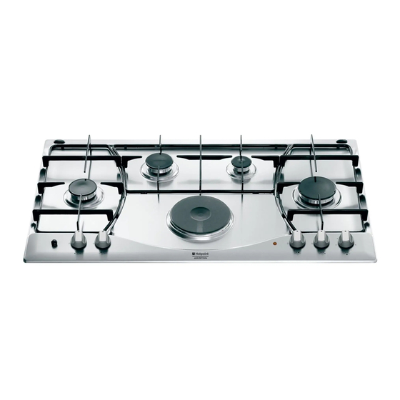
Hob Ariston PH 941MSTV için çevrimiçi göz atın veya pdf Kurulum ve Kullanım Kılavuzu indirin. Ariston PH 941MSTV 34 sayfaları. Built-in cooking table
Ayrıca Ariston PH 941MSTV için: Kurulum ve Kullanım Kılavuzu için Talimatlar (13 sayfalar), Teknik Özellikler (13 sayfalar), Kullanım Talimatları Kılavuzu (13 sayfalar), Kullanım Talimatları Kılavuzu (20 sayfalar)
- 1. Visto da Vicino
- 2. Come Utilizzarlo
- 3. Close-Up View
- 4. How to Use Your Appliance
- 5. Practical Advice
- 6. Is There a Problem
- 7. Safety Is a Good Habit to Get into
- 8. Installation Instructions for Built-In
- 9. Burners and Nozzle Specifications
- 10. Comment L'utiliser
- 11. Conseils D'utilisation
- 12. Caractéristiques des Brûleurs Et des Injecteurs
•
That the plug or switch are easily accessible.
Important: the wires in the mains lead are coloured in
accordance with the following code:
Green & Yellow
Blue
Brown
As the colours of the wires in the mains lead may not
correspond with the coloured markings identifying the
terminals in your plug, proceed as follows:
Connect the Green & Yellow wire to terminal marked "E"
or
or coloured Green or Green & Yellow.
Connect the Brown wire to the terminal marked "L" or
coloured Red.
Connect the Blue wire to the terminal marked "N" or
coloured Black.
Adapting the Cooktop for Different Types of Gas
To adapt the cooktop to a different type of gas than that
for which it was designed, (see the sticker under the hob
or on the packaging), the burner nozzles must be changed,
as follows:
•
Remove the pan supports and slide the burners out of
the cooktop.
•
Unscrew the nozzles using a 7mm socket wrench and
replace them with those for the new type of gas. (See
table 1, "Burner and Nozzle Specifications").
•
Reassemble the parts following the instructions in
reverse order.
•
On completing the operation, replace the old rating label
with the one showing the new type of gas; the sticker
is available from our Service Centres.
If the gas pressure is different than that prescribed, a
pressure regulator must be installed at the source, in
compliance with national standards governing the use of
piped gas regulators.
Regulation of Air Supply to the Burner
The burners do not need any primary air regulator.
Table1 (For Hungary)
Burner
Reduced Fast (RR)
Semi Fast (Medium) (S)
Auxiliary (Small) (A)
Triple Crown (TC)
Semi-FishBurner (SP)
Supply pressures
At 15°C and 1013 mbar-dry gas
P.C.I. G20
35,9 MJ/M
- Earth
- Neutral
- Live
Burners and Nozzle Specifications
G 20
Thermal power
Nozzle
kW
1/100 (mm)
2,45
110
1,60
96
0,90
71
3,15
133
1,50
95
25 mbar
3
Minimum Regulation
Minimum regulation:
•
Turn the gas valve to minimum.
•
Remove the knob and turn the regulator screw
(positioned either on the side of the top or inside the
shaft - Figs. A and B) clockwise until the flame becomes
small but regular.
N.B.: In the case of liquid gas, the regulation screw must
be fully screwed in (clockwise).
•
Make sure that, when the knob is turned rapidly high
to low, the flame does not go out.
•
In the event of a malfunction on appliances with the
security device (thermocouple) when the gas supply
is set at minimum, increase the minimum supply levels
using the regulator screw in Fig. A - B.
Once the adjustment has been made, apply sealing wax,
or a suitable substitute, to the old seals on the by-pass.
G 25.1
Thermal power
Nozzle
kW
1/100 (mm)
1,90
110
1,25
96
0,65
71
2,45
133
1,15
95
25 mbar
P.C.I. G30
122,8 MJ/M
P.C.I. G25.1
30,9 MJ/M
20
G 30
Thermal power
kW
1/100 (mm)
2,30
1,50
0,90
2,90
1,40
30 mbar
3
3
Nozzle
80
64
50
91
60