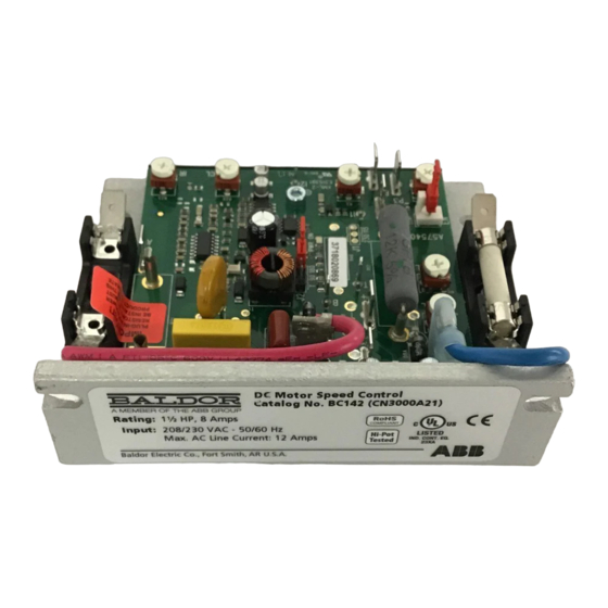
ABB Baldor BC142 Kurulum ve Kullanım Kılavuzu - Sayfa 15
Kontrol Ünitesi ABB Baldor BC142 için çevrimiçi göz atın veya pdf Kurulum ve Kullanım Kılavuzu indirin. ABB Baldor BC142 20 sayfaları. Dc control

Armature Switching and Dynamic Braking
If the armature is to be disconnected and reconnected with the AC power applied, connect a relay (or
contactor) and a brake resistor (RB) in the armature circuit. The Inhibit Circuit must be simultaneously
activated when braking. Wire a double pole double throw (DPDT) mechanically ganged switch to the
Inhibit Terminals and the relay (or contactor) coil.
When the switch is in the "Brake" position, the relay is deenergized and allows the motor voltage,
through N.C. contact, to be dissipated through RB and dynamically brake the motor. Simultaneously,
the inhibit is activated and the control output is electronically "extinguished", which eliminates arcing.
AC Line Input
When the switch is in the "Run" position, the N.C. contact opens, the N.O. contact closes, the Inhibit is
deactivated, and the motor begins to accelerate (according to the setting of the ACCEL Trimpot) to the
Main Speed Potentiometer setting.
Startup & Adjustments
The control has selectable jumpers which must be set before it can be used.
J1, AC Line Input Voltage Selection (Catalog No. BC142-5 and BC142-6 only)
Jumper J1 is factory set to the 230 position for 208/230 Volt AC line input.
For 115 Volt AC line input, set Jumper J1 to the 115 position, Figure 2-2.
Note: When Jumper J1 is set to the 115 position, Jumper J2 must be set to the 90 position (or the
T position if using a tachometer).
J2, Motor Voltage and DC Tachometer Selection
Jumper J2 is factory set to the "90" position on Catalog No. BC141, for 90 Volt DC motors, and set
to the "180" position, on Catalog Nos. BC142, BC142-5 and BC142-6, for 180 Volt DC motors. To set
Catalog No. BC142, BC142-5 and BC142-6 for step-down operation (208/230 Volts AC line input and
90 Volt DC output), set Jumper J2 to the "90" position). To set the control for tachometer connection,
set Jumper J2 to the "T" position (all models). See Figure 2-11.
Notes:
1. Catalog No. BC141, the "180" position is not available on Jumper J2.
2. Catalog No. BC142-5 and BC142-6, do not set the output voltage to 180 Volts DC when the
AC line input is set to 115 Volts.
2-8
Figure 2-11 Typical Dynamic Braking Circuit Connection
Speed Control
L1
L2
I1
N.O.
A+
A-
I2
Double Pole Double Throw
Run
Mechanically Ganged Switch
Brake
Run
Brake
Relay or
Contactor Coil
+
N.C.
Motor
M
Armature
RB
-
MN704
