Clarion PN-2302N-A Servis Kılavuzu - Sayfa 3
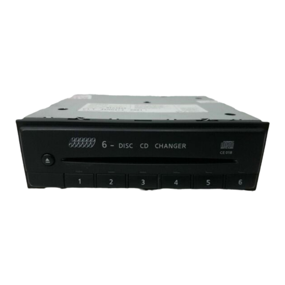
CD Çalar Clarion PN-2302N-A için çevrimiçi göz atın veya pdf Servis Kılavuzu indirin. Clarion PN-2302N-A 20 sayfaları. Nissan automobile genuine 6-disc cd changer deck
FEATURES
■
EXPLANATION OF IC
■
μ
PD78078GC-A13-8EU
052-5034-00 1-DIN 6-CD A/C Controller
1. Terminal Description
pin 1 : X Wr INH_
: IN : DRAM write inhibit signal input from
pin 2 : S DTO
: IN : Serial status data input from *SPMC.
pin 3 : X S O EN_
: O : Serial status data output enable signal
pin 4 : XLT_
: O : Latch pulse output to *SPMC. Negative
pin 5 : A VSS
: - : Ground for the internal ADC.
pin 6 : X RD EN_
: O : DRAM read enable signal output to
pin 7 : X WR EN_
: O : DRAM write enable signal output to
pin 8 : A Vref
: - : Not in use.
pin 9 : NDS RX D
: IN : NDS serial data input.
pin 10 : NDS TX D
: O : NDS serial data output.
pin 11 : NDS SRQ_
: O : NDS slave request pulse output. Nega-
pin 12 : VSS
: - : Ground.
pin 13 : SQSO
: IN : SUB-Q data input from CDX2548.
pin 14 : NU
: - : Not in use.
pin 15 : SQ CK
: O : Clock pulse output to read SUB-Q -
pin 16 : BEEP OUT
: O : Beep output 4.8kHz.
pin 17 : ILL_
: IN : Illumination ON signal input. Negative
pin 18 : Q TBC
: IN : Playback data time information input
pin 19 : NU
: - : Not in use.
pin 20 : Q R CK
: O : Playback data time information read
pin 21 : LOAD CW
: O : Disc loading / Drive unit transfer motor
pin 22 : LOAD CCW
: O : Disc loading / Drive unit transfer motor
pin 23 : Up/Dw CW
: O : Mode plate transfer / Stage up down
pin 24 : Up/Dw CCW
: O : Mode plate transfer / Stage up down
(
*SPMC. Negative logic.
output to *SPMC. Negative logic.
logic.
*SPMC. Negative logic.
*SPMC. Negative logic.
tive logic.
Data from CDX2548.
logic.
from *SPMC.
clock output to *SPMC.
control.
control.
motor control.
motor control.
(
pin 25 : SHAVE CW
pin 26 : SHAVE CCW
pin 27 : P ON 1
pin 28 : P ON 2
pin 29 : NU
pin 30 : DISC 1 KEY_ : IN : Disc 1 Key switch input. Negative log-
pin 31 : DISC 2 KEY_ : IN : Disc 2 Key switch input. Negative log-
pin 32 : DISC 3 KEY_ : IN : Disc 3 Key switch input. Negative log-
pin 33 : DISC 4 KEY_ : IN : Disc 4 Key switch input. Negative log-
pin 34 : DISC 5 KEY_ : IN : Disc 5 Key switch input. Negative log-
pin 35 : DISC 6 KEY_ : IN : Disc 6 Key switch input. Negative log-
pin 36 : EJECT KEY _ : IN : Eject key switch input. Negative logic.
pin 37 : S CLR_
pin 38 : S STB
pin 39 : S CLK
pin 40 : S DATA
pin 41 : LIM SW
pin 42 : ILL SEL_
pin 43 : VSS
pin 44 : DIM ON
pin 45 : MUTE
pin 46 : PT 1_
pin 47 : SW 3_
pin 48 : SW 1_
pin 49 : SW 2_
pin 50 : SW 4_
- 3 -
(
: O : Chuck and holder transfer motor con-
trol.
: O : Chuck and holder transfer motor con-
trol.
: O : "H"= Mechanism ON.
: O : "H"= CD play.
: IN : Connect to VDD.
ic.
ic.
ic.
ic.
ic.
ic.
: O : Clear signal output to Dual color LED
control.
: O : Strobe pulse output to Dual color LED
control.
: O : Clock pulse output to Dual color LED
control.
: O : Serial data output to Dual color LED
control.
: IN : Disc innermost track detection signal
input.
: IN : "H"= Without illumination control.
: - : Ground.
: O : "H"= Dimmer ON.
: O : "H"= Mute ON.
: IN : Mode plate position count photo cou-
pler input. Negative logic.
: IN : Shut door close detection signal input.
Negative logic.
: IN : Datum point detection signal input for
the mode plate. Negative logic.
: IN : Eject arm end detection signal input.
Negative logic.
: IN : Datum point detection signal input for
the wedge. Negative logic.
PN-2302M/N