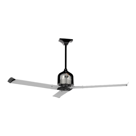
aerauliqa LHS240 Manuel - Sayfa 14
Fan aerauliqa LHS240 için çevrimiçi göz atın veya pdf Manuel indirin. aerauliqa LHS240 20 sayfaları.

trasnport foot
Fig. IV
Staffe di appoggio per
il trasporto in imballo
325
325
Fig. IV
295
295
Ø10.5
155
10,5
155
dimensions in mm of the
Fig. VI
brackets (3)
Fig. VI
Fig. VIII
Fig. IX
Fig.V
Fig. V
Dimensioni in mm delle piastre
di fissaggio a soffitto (3)
Fig. VII
8
8
8
10
10
9
9
14
14
12
12
11
19
19
14
Fig. VII
13
13
13
24
10
9
Fig. VIII
11
11
14
• Remove
transport feet from the
19
19
main body by unscrewing
the bolts, washers and
locknuts.
• Let
wires (17), hooking the
snap-hooks (19) to the
eyebolts of the motor
plate,
correct tightening. Check
that the wires (17) are
duly tensioned.
• Fix the assembly to the
ceiling/beam through the
18
18
8 holes on the brackets
(3); fix the security wire
to the ceiling/beam using
the clamps (18). Fixing
screws/plugs are not
supplied.
25
• I nsert the blade (13) over
25
the blade root, lock it with
the M8 flange bolts (8),
spring washers (10) and
locknuts (9). Tighten the
screws making reference
to table 1. Mount the
24
24
plastic caps (14) on the
locknuts.
blade terminals (24) by
means of the self-tapping
screws (25).
• Mount the plastic hub
cover (11) under the hub
using the M4 bolts (12).
In case water is used
for washing, drill a hole
in the plastic cover for
water drainage.
the
three
out
the
safety
verifying
the
Mount
the
