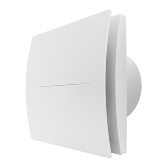
aerauliqa QD120 Kurulum Kılavuzu - Sayfa 4
Fan aerauliqa QD120 için çevrimiçi göz atın veya pdf Kurulum Kılavuzu indirin. aerauliqa QD120 16 sayfaları. Axial fan
Ayrıca aerauliqa QD120 için: Kurulum Kılavuzu (13 sayfalar)

• Turn off the main switch whenever a malfunction is detected or when cleaning.
• For installation an omnipolar switch should be incorporated in the fixed wiring, in accordance with the wiring regulations, to provide a full
disconnection under overvoltage category III conditions (contact opening distance equal to or greater than 3mm).
• If the supply cord is damaged, it must be replaced by the manufacturer, its service agent or similarly qualified persons in order to avoid a
hazard.
• Do not obstruct the fan or exhaust grille to ensure optimum air passage.
• Ensure adequate air return into the room in compliance with existing regulations in order to ensure proper device operation.
• If the environment in which the product is installed also houses a fuel-operating device (water heater, methane stove etc., that is not a "sealed
chamber" type), it is essential to ensure adequate air intake, to ensure good combustion and proper equipment operation.
• Install the product so that the impeller is not accessible from the air outlet side as verified by contact with the Test Finger (test probe "B" of the
norm EN61032) in compliance with the current safety regulations.
• Ceiling installation
In order to guarantee the IPX4 degree of protection against moisture in case of ceiling installation, use the appropriate ceiling mount kit, which
is not included. Use only the rear entry hole for supply cables. If there is a possibility of condensation along the air discharge duct, provide a
drainage system to prevent condensation from discharging into the environment through the fan.
Attention: do not mount the product on the ceiling without this kit.
• Window installation
In case of window installation it is necessary to use the appropriate window kit, which is not included.
Attention: do not mount the product on the window without this kit.
VERSIONS
STANDARD
The fan is operated using a separate ON/OFF switch or via a light switch (fig. 14A).
PULL CORD
The fan is operated using an integrated pull cord switch (fig.14C ).
WITH TIMER (over-run)
The fan is provided with a timer circuit which is adjustable from aprox. 1 minute to 25 minutes via trimmer (fig. 15B).
Operation: connected according to the diagram in figure 14B, after the light is switched on, the fan activates with a delay of max 1.5 seconds.
After the light is switched off, the fan continues to function for a pre-set period of time.
WITH HUMIDISTAT & TIMER
The fan is equipped with a humidity detector, whose threshold is adjustable from 50% to 95% Relative Humidity, and with a timer which is
adjustable from aprox. 1 minute to 25 minutes via corresponding trimmer (fig. 15D).
Turn the trimmer HY completely clockwise and the humidistat function is deactivated.
Automatic humidistat operation: connected according to the diagram in figure 14D, when the percentage of Relative Humidity exceeds the pre-
set intervention threshold, the fan starts up automatically. When the percentage of Relative Humidity goes below the threshold, the fan continues
to function for a pre-set period of time.
Operation with switch connection: connected according to the diagram in figure 14D, after the light is switched on, the fan activates with a delay
of aprox. 1.5 seconds. After it is switched off, the fan continues to function for a pre-set period of time.
Operation via pull cord switch (HTPC version): connected according to the diagram in figure 15C. By switching on, the fan activates with a delay
of aprox. 1.5 seconds. After switching off, the fan continues to function for a pre-set period of time
Attention: When the relative humidity level is higher than the pre-set threshold, automatic operation with humidistat has priority over manual
operation, or rather the fan cannot be stopped via switch.
STANDARD CONFORMITY
2006/95/EC Low Voltage Directive (LVD)
2004/108/EC Electromagnetic Compatibility (EMC),
in conformity with the following standards:
Electrical Safety
EN60335-1(2008); EN 60335-2-80(2005); EN 60335-2-80/A2(2009)
Electromagnetic Compatibility
EN 55014-1(2006)+A1+A2; EN 55014-2(1997)+A1(2001)+A2(2008)+IS1(2007)
EN 61000-3-2(2006)+A1(2009)+A2(2009); EN 61000-3-3(2008).
4
